Vibrant Alley – Revitalizing Dead Spaces


The urban environment combines various spaces and paths that are used by people everyday. However, the access to such spaces is filtered through different times of the day, particularly at dusk and night. These restrictions begin to construct an issue of accessibility to desired or needed spaces. Such locations can be defined as “dead spaces” or undesirable paths due to a lack of safety or control in the space. Therefore, the idea of this project is to design a system that allows for dead space to be accessible.

Our proposal is to create a space that can be desired as an accessible path for people, particularly in the interests of safety. To do so, we want to improve lighting as a means of attracting people into a space. The lighting is then a customary element of control for the user. In other words, the person walking through the space controls the motion and angles of soft light beams simply through their position in space. Conceptually, the number and angles of light being generated produce a canvas of light surrounding the user as well as creating a lit path for them to follow, and hence a desirable and safer space for one to use.

In our prototype, we purposes LEDs and servo motors to direct the lights based on an object’s position in the grid, but on a full scale model, a brighter beam would be necessary for the project.

In the first video, a close up of one servo can be seen–the motor’s movement redirects the light to each location.

In the second video, the motors can be seen sweeping from the left side to the right–they are alternately pointing to the leftmost pad, then the center, then the rightmost, with a short delay in between. Although we could not get the motion detection to work completely correctly, the motors do have the capacity to point to specific coordinates in a coordinated manner.

Screenshot 2014-12-15 11.42.22

finalvid [Concept Video]

-Tessa Crawford, Angelo Razo, Mathew Hoffman, Tanay Nandgaonkar

Space Jam: An Interactive Manipulation of Public Space Through Sound

Lonely Spaces

Many public spaces in our urban environments lack liveliness, and do not bolster interaction between people previously unacquainted.  With this project, our intent is to improve this potential for interaction through the amplification of connections.

Amplify Connections

With the use of music actuated as a background track via the presence of occupants, the space will utilize triggered samples matching the background track to give users the ability to add to the song, creating an additive composition of music, interaction, and whimsy.

Typology of Vibes


By collecting current weather information, we have designed our system to select a background track based on predetermined weather typologies reflecting the vibe of the day.  

Weather Typologies

This begins the experience, and also selects the array of additive samples to be triggered by occupants as they move through the space.  Using triggers within the paving field that are unlabeled initially evokes a sense of singular experience within the user.  With repeated movement through the space, however, users gain the opportunity to learn of their control over the stimulus.  This allows them to begin participating in many ways, both facilitated with other users, or as individual agents.

Parts Diagram 2

The system as a whole is activated through the use of a Passive Infrared Sensor (PIR), which detects when any person enters the space.  This triggers a collection of weather data from the weather shield integrated with the Arduino microcontroller.   The attributes of weather, humidity, light level, and barometric pressure, are compiled and converted to a binary signal to be used by our Processing code, which controls the music bank selection and playback.

Within the paving field, high sensitivity piezo film sensors detect the movement of users and send analog signals to the Arduino.  Using a sensitivity threshold within the Arduino code, the signal is sent to the Processing program as a cue to activate samples.  Having the sample bank already selected based on the weather information, these additive music samples match the background track in tone and feeling.  This leaves their timing to be controlled by the occupants, thus giving them control.


In the testing of our prototype, we took short videos of multiple stages of the system to demonstrate them as separate functions.  We used the simplified versions of these functions to test them, and then accumulated them into a full system.  Due to unpredictability of low quality piezo disks, the demonstration utilized buttons to convey intent of concept.  Videos of two weather typology sound banks are below:

Group Members:

Kevin Lenhart

Erica Nagy

Mariel Steiner

Patrick Webb

Battle Ship at Bus Stops

The purpose of ‘battleship at bus stops’ project was to develop a prototype that could be installed in public spaces to encourage social interaction through the use of games. The bus stop was chosen due to its temporal aspect which draws a number of individuals in one area for a brief period of time thus allowing for the opportunity to develop social interaction between strangers. Battle ship was chosen due to its turn based gameplay which allowed individuals to make their move one at a time.

Arduino_Battleship

Our project began by attempting to install individual micro controllers known as AT Tiny to light multiple LED’s on the game board but then we discovered that a range of LED’s connected to one wire was already available for purchase online so we decided to go with that instead.
Below is how we attempted to develop a communication with the AT Tiny and the arduino board.

Other components of the project include the Kinect which captures the movement of the players engaged in the battleship game and generates a digital pattern on the back face of the bus stop thus developing public art through the act of social interaction.

This is how we researched how to develop our project through the use of the kinect:

The prototype of the board was developed with the use of the arduino board to develop the circuit and a potentiometer to switch between the LED grid by varying voltage values.

We intend to develop this project further by implementing games in spaces like the bus stop which draw public activity and create opportunities for social interaction.

Team Members:

Eleanna Panagoulia
Mohammad Momenabadi
Namju Lee
Shahzada Mustafa Ahmad

Interactive Digital Matrix

Why:

Our project takes simple components that can be used to motorize any operation and control it with motion.  We have focused our  efforts on the  issues of the modern human who needs to be socialized  in group work. Our proposed installation can be placed anywhere in a city designated to gather people for interaction. The use of the Arduino modernizes the mediums that are used in traditional installations and allows city dwellers to interact with  the space around them and people. The chime installation will produce different sounds in each  of the five rows. Each row will be controlled by a different Arduino and Leap Motion, allowing up to five people to work together to create a rhythm  with different notes.
This type of installation would be best used during welcoming or team building events. For example, the CED open house or school events during the beginning of the semester that are meant to welcome new people into a community or group. The moving matrix can be used as a fun, large scale ice breaker for groups of five people to interact with each other. If particular goals are set for the users, for example to make a familiar tune by coordinating row tempos, the installation can be used for team building purposes.

 Work flow:

work flow
work flow

Take gesture as input, and the whole working process is based on the transition from gesture to physical visualization. It’s accomplished step by step, as the work flow chart shows above.

Gesture Capturing

The device we used to capture gesture is leap motion. Based on the previous post about the processing library of leap motion, we are able to utilize the vector(including speed, position and so on) acquired by leap motion to do further visualization process.

Wave Visualization 

Design Space of wave patterns


Working on the visualization of vectors captured by leap, we decide to use the wave patterns. Above is a design space of some possible wave patterns generated.

The code concerning the wave simulation process can be accessed through the previous post of “Wave Simulation in Processing”.

We have chose the wave pattern we deem works best based on the design space , and simulated the movable pattern using processing. Here are two video of that simulation, in either 2D and 3d.


LED Matrix test

The LED matrix can be used to physically display the visual data from processor. It also serves as a test for the circuitry and coding.  The concept of an LED matrix could be used instead of a motorized system for an installation, especially if it is to be a night installation, say for the winter holiday season. The concept of interaction of the user with the installation and others in the space can also be accomplished with  an LED matrix.

Untitled-1

The details concerning the LED matrix can be accessed through “How to Build a 5X5 LED Matrix”.

Here is a video about our Multi-LED test:


 Multi-Servo Test

This process is the way to turn data acquired by leap motion into physical movement. It is also the bridge of digital to physical.

We tested the possibility of controlling 4 servo’s movement based on the position of gesture.

circuit
circuit

Here is the video showing the controlling process.

 Physical installation

In order to convert the rotation of servo or motor, we have designed the physical installation of pulling balls by motor.

set big per top

/Users/JERRY/Desktop/MyBat_Shapeoko_004_Y_Axis_Motor_Mount_Plate set small


Team member:

Wenzhe Peng | Janet Torres | Jianjia Xu | Yuqing Nie

Particle Wave – Using light to reveal air quality and wind

Particle wave is a prototype installation that uses a string of LEDs, sensors, and Arduino microcontroller to reveal spatial and temporal changes in air pollution in the urban environment. The ultimate goal of the project is to create an array of poles that could be installed in vacant lots near freeways or other sources of urban air pollution.

Arduino_FinalBoard_12-10

Our first prototype works!

In the future we plan on using more accurate pollution sensors, refining the way that data is expressed through the RGB LEDs, and considering the deployment of similar device throughout the urban fabric instead of solely as a temporary art exhibit.

Team Members:

Joe Burg

Elaine Laguerta

Kyle O’Konis

Grant Saita

Project: Phase 2

Now it’s time to share your project! You’ll do that in class and on the blog.

In class

On December 11, 10a – 1p, you’ll present your final project in 108 Wurster (NOT our usual room, though it also has a nice projector, speakers, and space to pin up).  You will have 12 minutes for your presentation and 15 minutes for questions.

In your presentation, please include:

  • Your project title
  • The problem your project responds to
  • Why your project is the solution
  • How your project solves that problem

You should spend only a couple minutes on the first 3 bullet points, but this intro is very important. If you don’t grab the audience and interest them in the why of your project, no one will care what you did. Do not skip this. (Here’s a smart TED talk on that subject — worth the 18 minutes of your time.)

After the intro, the bulk of your presentation should describe how your project works. You may present your project as your group wishes, but you must include the following two items:

  1. A concept diagram (revised accordingly from Phase 1)
  2. A short video of your Arduino project in action

In your presentation, you may also choose to do a live demo with your Arduino project. Even if you do a live demo, it is still important to show the video because (a) the small Arduino projects are often difficult for everyone to see and (b) live demos may not work (Murphy’s Law).

Your audience will be the class, Professor Mozingo, Professor Kyle Steinfeld (Architecture), and Andrea Gaffney (Gehl Studio/LAEP Lecturer). I don’t have confirmation yet, but Professor Paulos and Professor Nicholas de Monchaux may also stop by.

On the blog

By noon on Dec 15, please have one member from your group post your concept diagram and video. (Please don’t be late.)

You may post any additional text or materials that your group wishes to include, so that you can proudly share the link with your friends and/or future employers.

Follow the instructions you used for posting your tutorial, with one change: please check the Projects box in the Categories menu.

wordpress_categories_projects

Thank you all for a wonderful semester. I’m so proud of you!

How to build a 5X5 LED matrix

Janet's LED matrix

This tutorial will cover the basic knowledge you need to hack your way at a self-made LED matrix. We will use open source instructions available online from various groups to learn about the components of this kind of project and to acquire code to control the LED matrix. Various sources for each of the components will be given. As will become apparent, there are many ways to solve a circuitry problem. Our main “problem” when making a 5X5 LED matrix is the limited number of Arduino output pins we have to control it. In this tutorial we will be controlling 25 LEDs using Shift registers and NpN transistors to minimize the number of Arduino pins needed to control the lights.
Your needed materials are:
– 1 Arduino Uno
– 2 Shift registers (I use 74HC5950)
– 10 NPN transistors (BC547)
– 5 1kohm resistors (for base of transistors)
– 10 100 ohm resistors (for the emitters of the transistors)
– 25 LEDs ( I use blue)
– Lots of wire
– Solder and soldering iron
We will start by watching a video that covers the basics. [ VIDEO: https://www.youtube.com/watch?v=GPokkuX_jjk ]
The main concepts from the Make video by Collin Cunningham are:
• LED matrix ( powering and controlling LEDs through columns & rows)
• How to bend the anode and cathode legs to create LEDs in parallel to create your own matrix
• Multiplexing using a serial LED display driver
Collin Cunningham gets fancy and uses an already build LED matrix and even makes his own printed circuit board. In order to lower costs we will be using some different methods to multiplex, but this video is by a charismatic character who quickly shows the process.
The initial inspiration for the configuration used in this tutorial comes from instructables.com by user Osgeld. [ HACK: http://www.instructables.com/id/The-74HC164-Shift-Register-and-your-Arduino/?ALLSTEPS ] The user goes through 3 possible projects using Arduino and Shift registers. The third project is the matrix controlled by using a shift register and transistors. He provides code for this configuration, which is always nice. The following two figures show the logic and circuitry behind the hardware.

osgeld circuit

Figure 2 Circuit by Osgeld on the Instructables page

Shift register Daisy chain

Figure 3 It is helpful to have a circuit diagram to help you as you wire

YouTube user Andrew Ong produced a great video that shows his digital model of a similar configuration. [ VIDEO: https://www.youtube.com/watch?v=2m3PbCvcqkY ] He points out the importance of choosing the right components to avoid a dimming effect and explains how the signal moves through the circuit.
If you work well with text this online Arduino workshop has a good explanation of LED matrices. http://www.thebox.myzen.co.uk/Workshop/LED_Matrix.html
As you can see there are 5 components to this project: the Arduino, shift registers, transistors, LEDs, and of course resistors. We already know about the Arduino, so we need to give homage to electrical engineers and watch some videos that explain the necessary components needed to multiplex with LEDs. The videos will explain (in varying depth) the uses, coding, and mechanism behind each component. It is helpful to have the data sheets of the components you are using while watching these videos. You should also pay attention to the symbols they use when drawing the circuits, it will help you learn how to interpret circuit diagrams for future projects.

LEDs and resistors:
EEEnthusiast is a user of YouTube, he produces very thorough explanations on electrical topics. His video “Arduino Tutorial #1 – Extended – Limitations I/O pins, Pull-down, Current Resistor Calculations” explains current resistor calculations with Arduino.(https://www.youtube.com/watch?v=gGDq_-WKMfE&list=UU6JpBeS_6JhUwfGF8RgLCIQ)
A great follow up is “Resistance for LEDs Tutorial” by YouTube user Kevin Darrah. He explains the calculations needed to choose a resistor for your LEDs, although you use the same principle to calculate for other components as well. If you need additional help understanding resistors he has several other videos explaining their use and he points out the different symbols used when drawing circuits. When you are ready, he also has instructions on building other fun things like LED cubes. (https://www.youtube.com/watch?v=7PzohqhABj4)
When you are ready to calculate the resistant using Ohms law, there are handy websites (like http://www.ohmslawcalculator.com/led_resistor_calculator.php ) that can help you.
Transistors
Kevin Darrah also has a video explaining multiplexing LEDs with transistors that explains the hardware and software for controlling a matrix. https://www.youtube.com/watch?v=lZyc6ulpkyM There are may other videos that explain transistors, I recommend other by EEEnthusiast and Kevin Darrah such as:
‘How to work with Transistors’ by Kevin Darrah: https://www.youtube.com/watch?v=6RN1hnwBj3Y
‘How to Multiplex/ Part II’ by Kevin Darrah: https://www.youtube.com/watch?v=-1UPPHjR0vk&src_vid=lZyc6ulpkyM&feature=iv&annotation_id=annotation_397974
He explains why you use resistors on transistors, and how to multiplex the transistors to control the cathode and anode columns and rows.
‘Arduino #11 – High Current & Voltage Loads Tutorial – Transistors and Relays’ by EEEnthusiast (IF you are working with components that need higher voltage): https://www.youtube.com/watch?v=JJB_ICWYIqg&list=UU6JpBeS_6JhUwfGF8RgLCIQ
GarageLabe.com posted a tutorial on an 8×8 matrix that gives the best explanation on using transistors to create the persistence of vision effect that allows us to multiplex LEDs. It goes through the logic of coding for LEDs in parallel. The post also contains the basic layout of code to control a matrix using transistors. http://garagelab.com/profiles/blogs/arduino-scrolling-text-marquee-to-give-a-happy-christmas

Shift registers
The shift registers in the 5X5 matrix we want to build will allow us to control all 25 LEDs from 3 pins on Arduino. The 74HC595 is an integrated circuit that has 8 outputs, we need two of them because we have 10 transistors that will need to be connected to it. The transistors themselves are each connected to a row or column controlling 5 LEDs. You can also get some shift registers that have many inputs if what you need for a project are additional ins.
‘Arduino Tutorial #3 – Shift Registers (74HC595)’ by EEEnthusiast has a thorough explanation of coding for shift registers as well as the configuration for the 74HC595 model https://www.youtube.com/watch?v=bqfPZXEuyuc

Need more? Try:
74HC595 Shift Register Control | AVR Tutorial by 000Plasma000 https://www.youtube.com/watch?v=d7Au3I4ZdZc
‘Multiplexing with Arduino and the 74HC595’ by amandaghassaei
http://www.instructables.com/id/Multiplexing-with-Arduino-and-the-74HC595/step2/How-does-the-74HC595-work/
A very similar circuit and code that is easily adapted
http://tronixstuff.com/2010/06/06/getting-started-with-arduino-chapter-nine/

Soldering
When building your own LED matrix it is important to solder the components appropriately. Watch this quick video by Collin Cunningham to get all the basics on soldering. https://www.youtube.com/watch?v=QKbJxytERvg
It is important when building a matrix that the row and column wires do not touch. This can be accomplished by using electrical tape to protect on of them from the other, as I have done. Alternatively, this can be accomplished by bending them appropriately to create a space between the two, as seen in this image from instructable.com

Separating Cathodes and Anodes

Figure 4 http://www.instructables.com/file/FLQPWTJFHAVXW8W
Now that you have your matrix built and connected test out your grid using test code. You will have to modify the code to match your wiring. I wanted to test the circuit so I adapted code from tronixstuff.com just to make sure the LEDs were getting power. For my matrix, one shift register controls cathodes and another the anodes
//// Modfied from http://tronixstuff.files.wordpress.com/2010/06/example9p1.pdf
int latchpin = 4; // connect to pin 12 on the ‘595
int clockpin = 3; // connect to pin 11 on the ‘595
int datapin = 2; // connect to pin 14 on the ‘595
int matrixrow[5] = {
1,2,4,8,16};
int matrixcolumn[5] = {
1,2,4,8,16};
void pixeldisplay(int row, int column, int holdtime)
// turns on and off a pixel at row, column – with delay ‘holdtime’
{
digitalWrite(latchpin, LOW);
shiftOut(datapin, clockpin, MSBFIRST, matrixcolumn[column-1]); // sets the digit to address
shiftOut(datapin, clockpin, MSBFIRST, matrixrow[row-1]); // clears the digit
digitalWrite(latchpin, HIGH);
delay(holdtime);
}
void rowdisplay(int row, int holdtime)
// turns on and off a row of LEDs with delay ‘holdtime’
{
digitalWrite(latchpin, LOW);
shiftOut(datapin, clockpin, MSBFIRST, 255); // we want all the cathodes on, which is 11111111 in binary, 255 decimal
shiftOut(datapin, clockpin, MSBFIRST, matrixrow[row-1]); // clears the digit
digitalWrite(latchpin, HIGH);
delay(holdtime);
}
void columndisplay(int column, int holdtime)
// turns on and off a column of LEDs with delay ‘holdtime’
{
digitalWrite(latchpin, LOW);
shiftOut(datapin, clockpin, MSBFIRST, matrixcolumn[column-1]);
shiftOut(datapin, clockpin, MSBFIRST, 255); // we want all the anodes on, which is 11111111 in binary, 255 decimal
digitalWrite(latchpin, HIGH);
delay(holdtime);
}
void setup()
{
pinMode(latchpin, OUTPUT);
pinMode(clockpin, OUTPUT);
pinMode(datapin, OUTPUT);
}
void loop()
{
for ( int a = 1; a < 10; a++) {
for ( int b = 1; b < 10; b++) {
pixeldisplay(a,b,50);

for ( int a = 1; a < 10; a++) {
for ( int b = 1; b < 10; b++) {
pixeldisplay(b,a,50);
} } } } }

Playing an Audio File with Processing

In this tutorial, we will demonstrate how to use Processing to play an audio file of your choise. We intend to use this function as part of a larger project involving the use of sensors in public spaces to trigger pre-recorded sounds when people pass through the space. In this larger project, the function we describe here will be linked with the function of using a piezo sensor to detect vibration.

INGREDIENTS:
Arduino UNO
Processing software
IMG_3248 Processing code

While it is possible to use arduino to play individual audio files in mono, Processing allows for the playback of audio files in stereo, and can overlap multiple audio files at once.

To clarify this terminology, “mono” means the audio file has a single audio channel, as opposed to the left and right audio channels of stereo audio files. Virtually all contemporary music is formatted in stereo, and it is the format we are accustomed to listening to.

Processing is capable of performing these magical feats of musical playback by virtue of the Minim library. Minim comes included with Processing software. It can also be used outside of Processing, but we’re not going to get into that here.

The only assembly required to run this function is to connect your arduino to a computer via usb. Do this now.

Next, open a new Processing file. Save it under your file name of choice (I called mine “Minim_1”). When you save, a folder will be generated to contain your Processing file. This folder will have the same title as your processing file.

Next, select an audio file, something short. Place your audio file in the Processing folder that you just generated. We chose a Napalm Death song titled “You Suffer”, which lasts about 3 seconds. It’s amazing, and downloadable here if you want to use my code.

If you do use this file, re-title it “you_suffer.mp3”, place it in your Processing folder, and use the code I provide below.

If you wish to play a different audio file, this link provides you with code to do so, as well as lots of helpful info about Minim.

To play the audio file you have now placed in your Processing folder, simply plug it in to the code provided by the link by deleting the song title they have in quotes (“mysong.wav”), and typing in the file name of your audio file between the quotes (e.g. “you_suffer.mp3”).

Here is the code we used:

That’s it on your end, the code handles all the rest of the work, importing the Minim library and using an audio player function to play your audio file.

When you run the code, a small window will appear to the side, and your audio file will play. It looks like this:Processing2

Happy jamming!

Using Piezo Sensors to Detect Vibration

Using Piezo Sensors to
Detect Vibration

In this tutorial, you will learn how to use a Piezo sensor to detect vibration. We intend to use this function as
part of a larger project involving the use of sensors in public spaces to turn on background music and trigger
pre-recorded sounds when people pass through the space. To keep things simple, however, this tutorial will
stick to the simpler concept of the film sensor perceiving vibration.

IMG_3115


INGREDIENTS:
• Arduino UNO
• Solderable breadboard
• (1) LM358 OpAmp
Integrated Circuit
• (1) Piezo sensors
• (1) Potentiometers
• (1) 1 mega-ohm resistor
• (1) Zener 5.1V 1 Watt diode
• (1) 0.1 uF capacitor
• Jumper wires

The first step is to put your circuit together.
The image below shows the completed circuit using a solderable breadboard.
In the bottom left of the image the green and yellow wires are coming from the piezo element. The yellow is
the ground, the green is the positive output. A resistor is used for the component. To prevent voltage spikes,
a diode is added in parallel to protect other parts of the circuit.
The signal is taken into the op amp. The op amp amplifies the signal from the piezo element, and sends
that signal from one side of the op amp to the other. The right side of the op amp receives the signal, and is
used for amplification of the signal. The left side gets the amplified signal from the right side, and is used for
a comparator, determining which values to designate as high or low. The potentiometer adjusts the sensitivity
of the comparator, and thus the sensitivity of the trigger.
The output of the comparator provides the input for the arduino. Using our code, this input determines the
display in the serial monitor, either “EARTHQUAKE” when motion is detected, (a HIGH reading) or “CHILLIN”
when motion is not detected (a LOW reading).Piezo Diagram

This diagram illustrates the flow of the signal through the circuit:


Tutorial 3_Circuit Diagram

The completed code and serial monitor display look like this:

Code and Serial Monitor


Detecting the absence of light to gradually switch on LED(s).

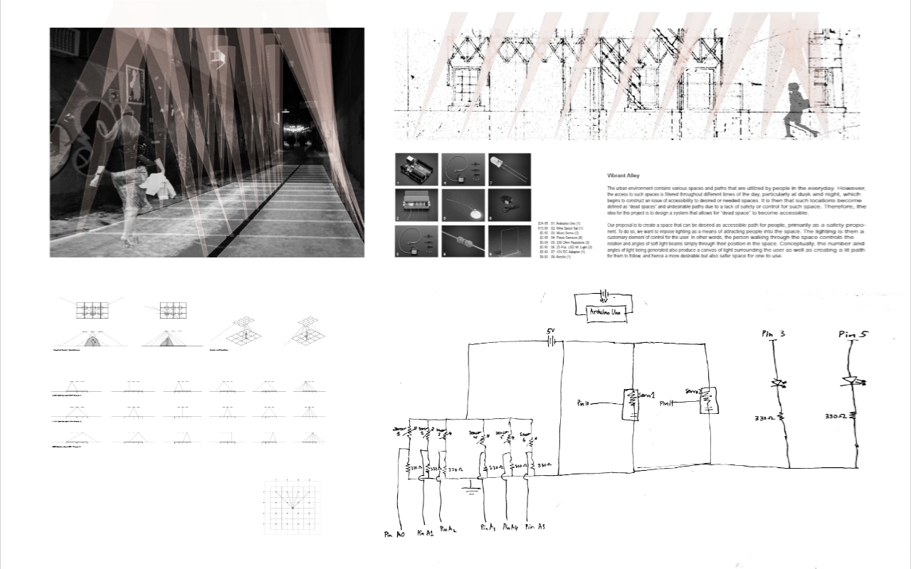
In this tutorial we will be looking at how to use a photo resistor to turn on an LED light with the absence of light. this is useful for when the sun goes down and you need that extra light for a sense of comfort, or for generating an ambient setting in any space. This applies directly to a project that i am working on with a group in which we will be activating a dead space such as an ally way and providing a sense of safety at night time. With the small application applied to our greater idea we will be able to generate an ambient light to encourage people into a feeling of a safe environment.

To begin we will need all the parts listed below.

PARTS LIST
* 1 X Breadboard $4.95
* 1 X Arduino Uno $29.95
* 1 X LED pack $2.95
* 1 X 330 Resistors $0.95
* 6 X Jumper Wires $4.95
* 1 X Photo Resistor $1.50
* 1 X 10 K Resistors $0.95
Total = $46.20 (tax and shipping not included)

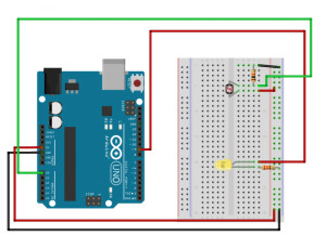
step 1: HARDWARE CONNECTIONS
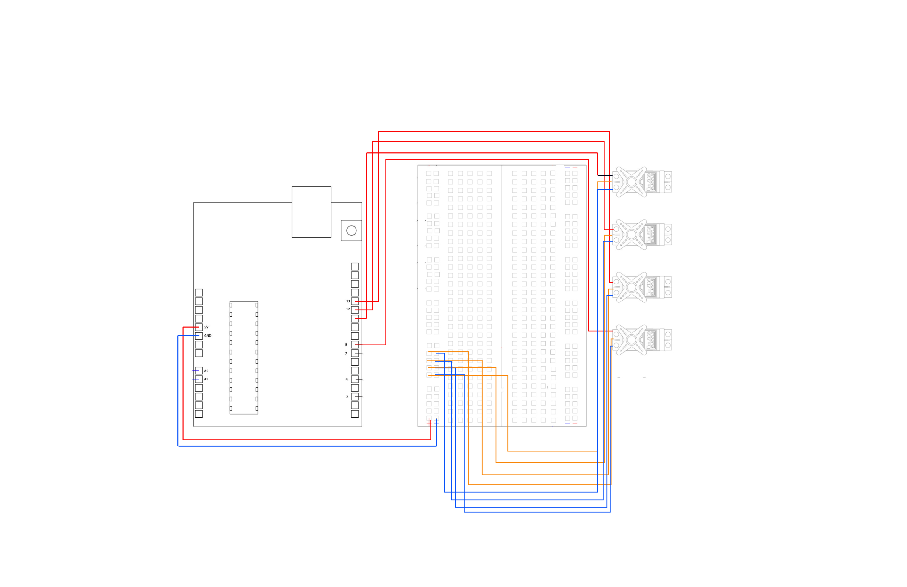
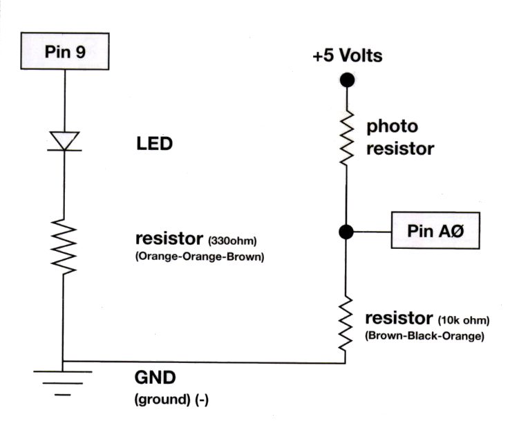
taking the Photo resistor you’ll need to connect one side of the photo resistor to 5 volts labeled on your arduino as (5V). Next take the other end and connect it to the analog pin 0. You no want to create a voltage divider by connecting a 10K resistor between ANALOG pin 0 and the ground or GND. This is now a voltage divider, with the photo resistor being one of two dividers. What this allows is for the output of the voltage divider to vary in the light level.
LED: now connect the positive side (long leg) of the LED to digital pin 9. (To vary the brightness, this pin must support PWM, which is indicated by “~” or “PWM” on the Arduino itself.)
Connect the negative side of the LED (short leg) to a 330 Ohm resistor.
Connect the other side of the resistor to GND.
this is a simple diagram to help explain its set up construction for piecing together the parts into a functional process.
fritzing diagram

——-
Step 2: Const int
Now that you have all the pieces connected we will designate your constant integers. Start by typing out “const int” it should highlight itself and after adding a space designate which pin the photo resistor will be sensing from in its analog output. After typing that first const int repeat the process with const int ledpin = 9; and don’t forget to end it with a semicolon.
Now we will also set up some global variables for the light level:

“int lightlevel, high = 0, low = 1023;”

This is telling the arduino the voltage boundaries.

——-
Step 3: void setup()
Begin your next line of code by typing “void setup()” press enter and start the next line with a curly bracket
“{”
(Again look ahead below in this tutorial to get a clear idea of how i’m referring to the code.)
next you will press enter again to start the next line and type in “pinMode(ledpin, OUTPUT);”

It is case sensitive so make sure that the variables you are using are the same as the ones you previously defined.
Press enter again and close off the void setup with a closed curly bracket “}”

——-
Step 4: void loop()
Start your next line by typing in “void loop()” and then enter. Your next line should be a curly bracket

“{“.

Next comes something possibly new. It’s called “analogread”. It measures the voltage coming from the photo resistor and resistor pair. This number can range between 0 (0 volts) and 1023 (5 volts), but this circuit will have a smaller range between dark and light.
So after that curly bracket has been placed as mentioned previously you want to then start your next line and type in

“lightLevel = analogRead(sensorPin);”

Remember to pay close attention to what is capitalized and what is not based on what you have designated in your global integers and constants.

So now we want to use this number to control the LED. But we have a problem: the analogRead() function returns values between 0 and 1023, and the analogWrite() function wants values from 0 to 255.

We can solve this by using two handy functions called map() and constrain(). Map will change one range of values into another range. If we tell map() our “from” range is 0-1023, and our “to” range is 0-255, map() will squeeze the larger range into the smaller. (It can do this for any two ranges.)

i.e. lightLevel = map(lightLevel, 0, 1023, 0, 255);

Because map() could still return numbers outside the “to” range, (if they’re outside the “from” range), we’ll also use a function called constrain() that will “clip” numbers into a given range. If the number is above the range, it will reset
it to be the highest number in the range. If the number is below the range, it will reset it to the lowest number. If the number is within the range, it will stay the same.

i.e. lightLevel = constrain(lightLevel, 0, 255);

Here’s one last thing to think about. The circuit we made won’t have a range all the way from 0 to 5 Volts. It will be a smaller range, such as 300 (dark) to 800 (light). If we just pass this number directly to map(), the LED will change brightness, but it will never be completely off or completely on.

so your next line of code should read as follows

“manualTune();”

This allows you to manually change the range from light to dark. now press enter to prepare for your next line of code.

The above functions will alter lightLevel to cover the range from full-on to full-off. Now we can adjust the brightness of the LED by typing in your next line of code

“analogWrite(ledPin, 255-lightLevel);”

By having lightLevel in this analog write segment being changed to 255-lightLevel it is now able to brighten the LED with the absence of light.
next you’ll press enter and end this void loop() with a closed curly bracket

“}”

step 5: Manual tune
you are now defining the variable manual tune and describing in code to the arduino what it means to have manual tune.

Begin a new line of code with:

“void manualTune()” press enter for a new line and type:

“{”

to signify the beginning of its definition.

next type:

“lightLevel = map(lightLevel, 0, 1023, 0, 255);”
“lightLevel = constrain(lightLevel, 0, 255);”

You can change the 0 and the 1023 for a different range of output in light intensity.
Now you want to return the main loop (), and send lightLevel to the LED. close this definition off with a curly bracket and your code is complete

“}”

compare to the code below for reference in how it is layed out.

———

CIRCUIT DIAGRAM

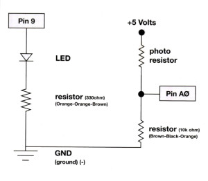
circuit diagram of a Photo resistor.

In this diagram, it is showing how you’ll be using a photo resistor. A photo resistor changes resistance based on how much light the sensor receives. Since our Arduino’s cannot interpret resistance directly, rather it reads voltage, we use a voltage divider to use our photo resistor. This voltage divider will output a high voltage when it is not getting any light or it will output a dim light when light begins to fade. in opposition, its output is a low voltage when it is receiving light. if tweaked right its low voltage will not be read and will be perceived as “off”.

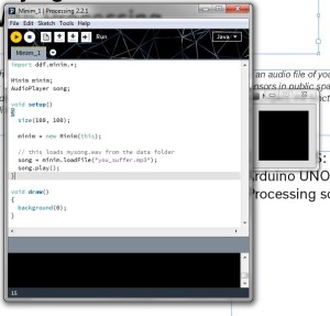
Here is an example of what your code should look like.

——-
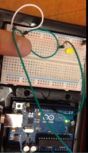
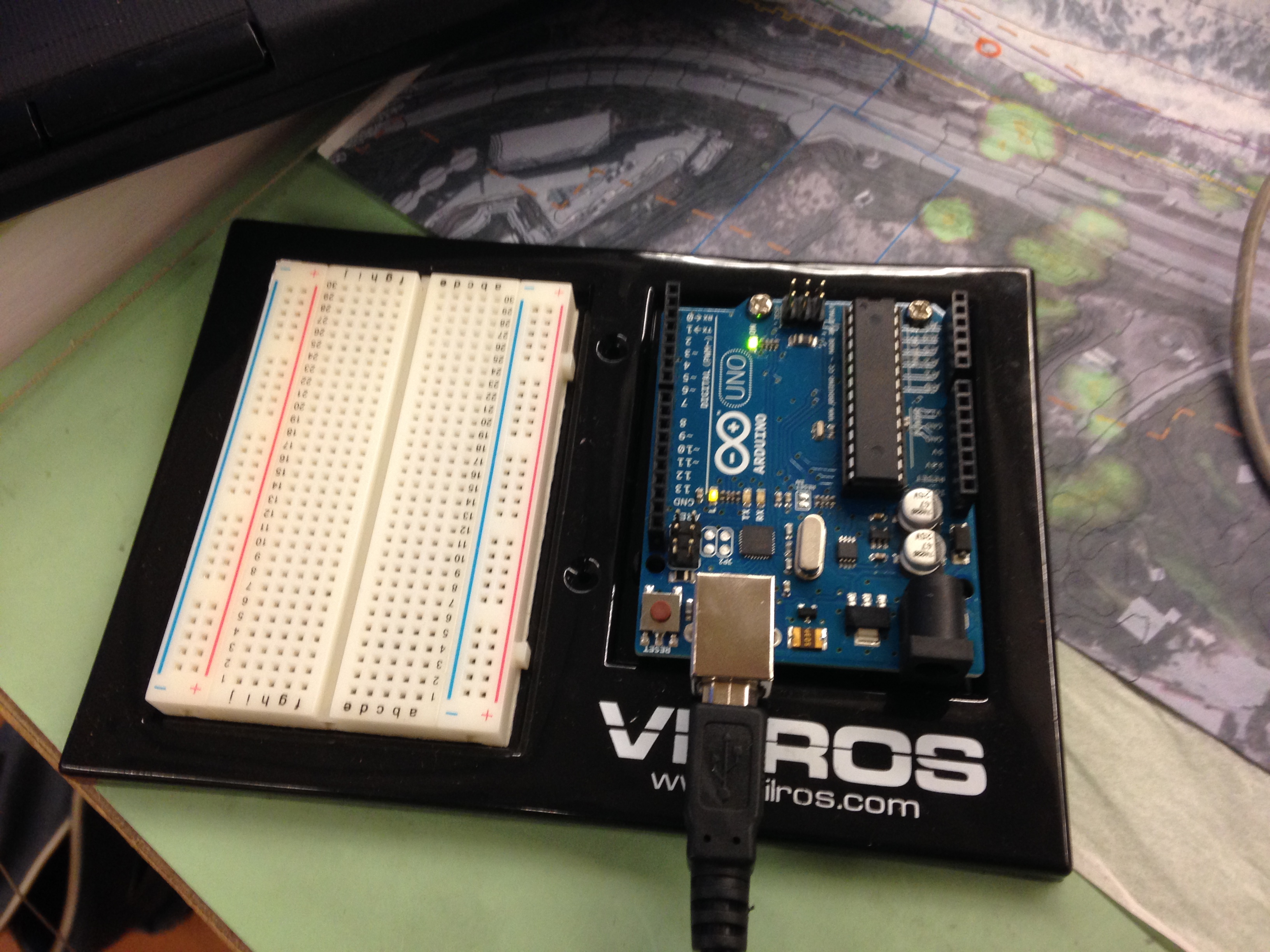
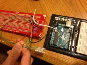
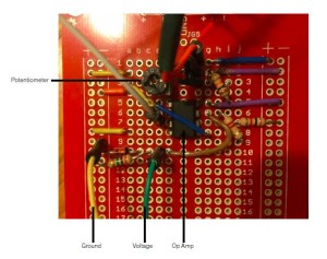
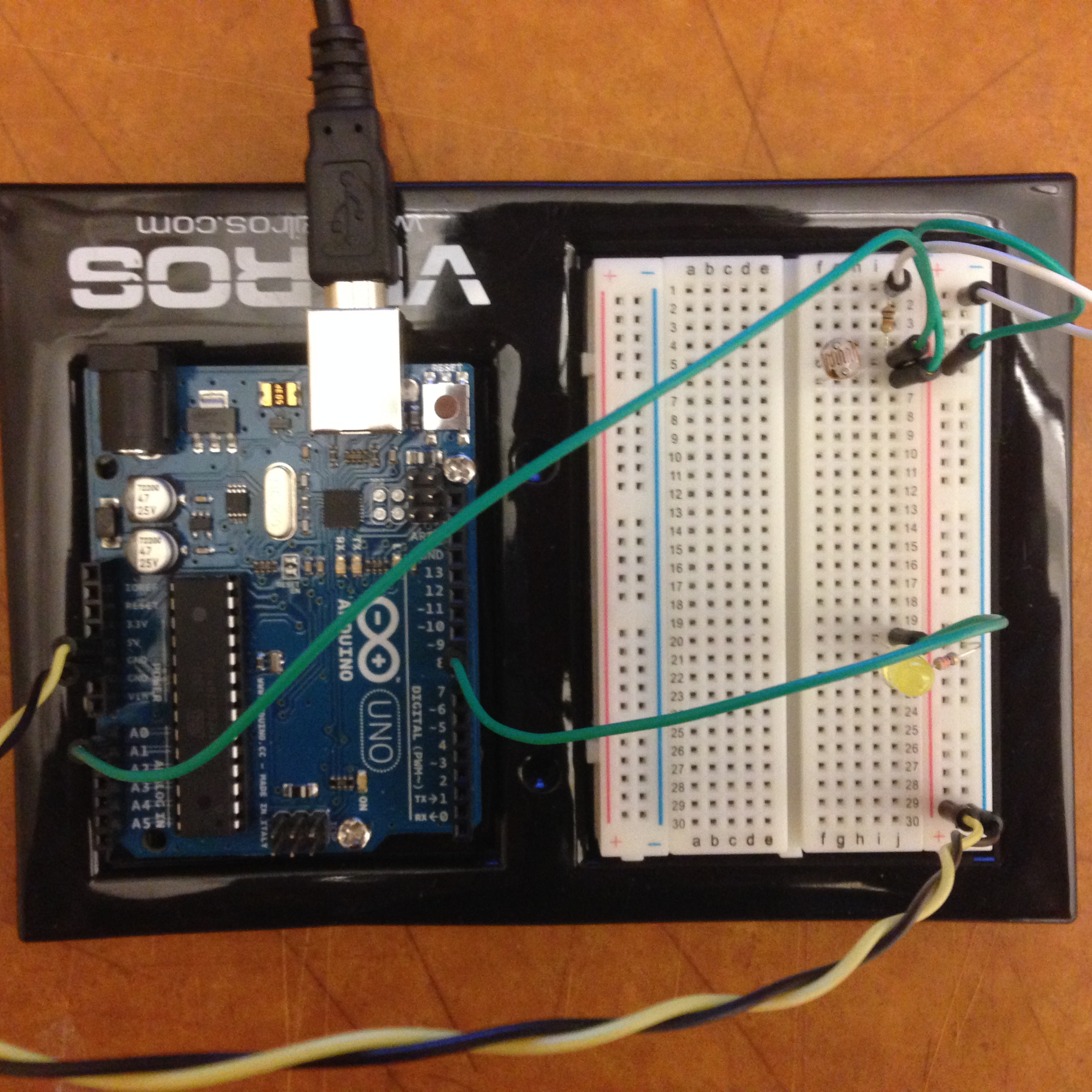
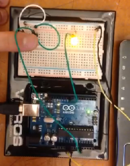
this would be a physical construction of the arduino board set up to sense an absence of light.

photo

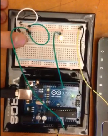
here are some photos of it in action in which a the photo resistor detects light and is not active or has a low output.
light detected no led 1

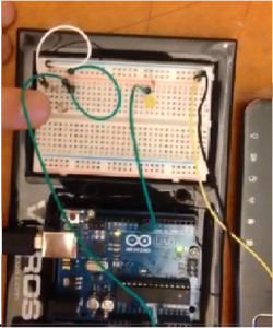
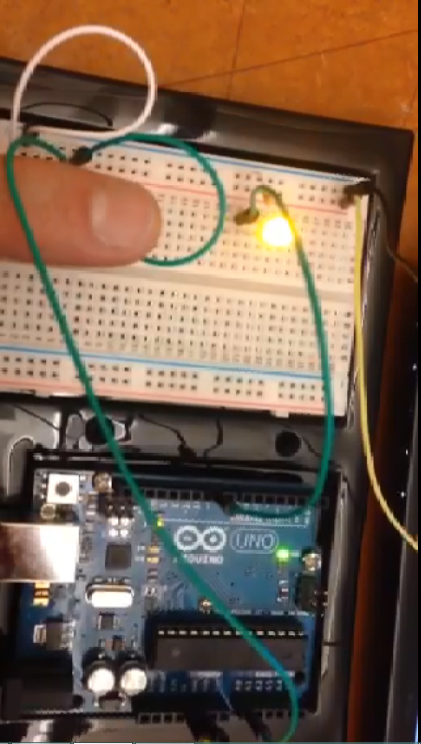
now with my finger barely covering the photo resistor the led starts to grow in its output of energy.
no light detection 2

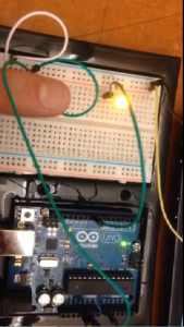
i am now covering the photo resistor in an attempt to mimic full darkness in which now the LED is at a full glow.
no light full glow 3

again i remove my finger barely to allow the photo resistor to receive a pinch of light which in turn lowers the output of energy. the bulb is at a low glow now, and then placing it back over the photo resistor once more allows the arduino to register a high low voltage and its output then becomes higher through the LED.
low light detection  low output 4no light detected full glow 5

Environmental Sensing and Responsive Design