Introduction
Spreadsheets are awesome! They are a ubiquitous and powerful file structure that can cause headache and joy in equally heart-stopping intensities. Within the context of a larger project, you may want to save Arduino data (from sensors, for example) to a .csv file for further analysis, visualization, or whatever spreadsheet bonanzas you can dream up. The following two sketches save data from Arduino to a .csv file on your computer, complete with a timestamp with gloriously specific column names (year, month, day, hour, minute, second…and you can add milliseconds!).
This 2-sketch solution takes advantage of the built-in Table class in Processing. Tables are also awesome, as they are basically spreadsheets in the Processing world. Read all about them (this link has some handy methods for working with tables beyond what this tutorialprovides): http://processing.org/reference/javadoc/core/processing/data/Table.html
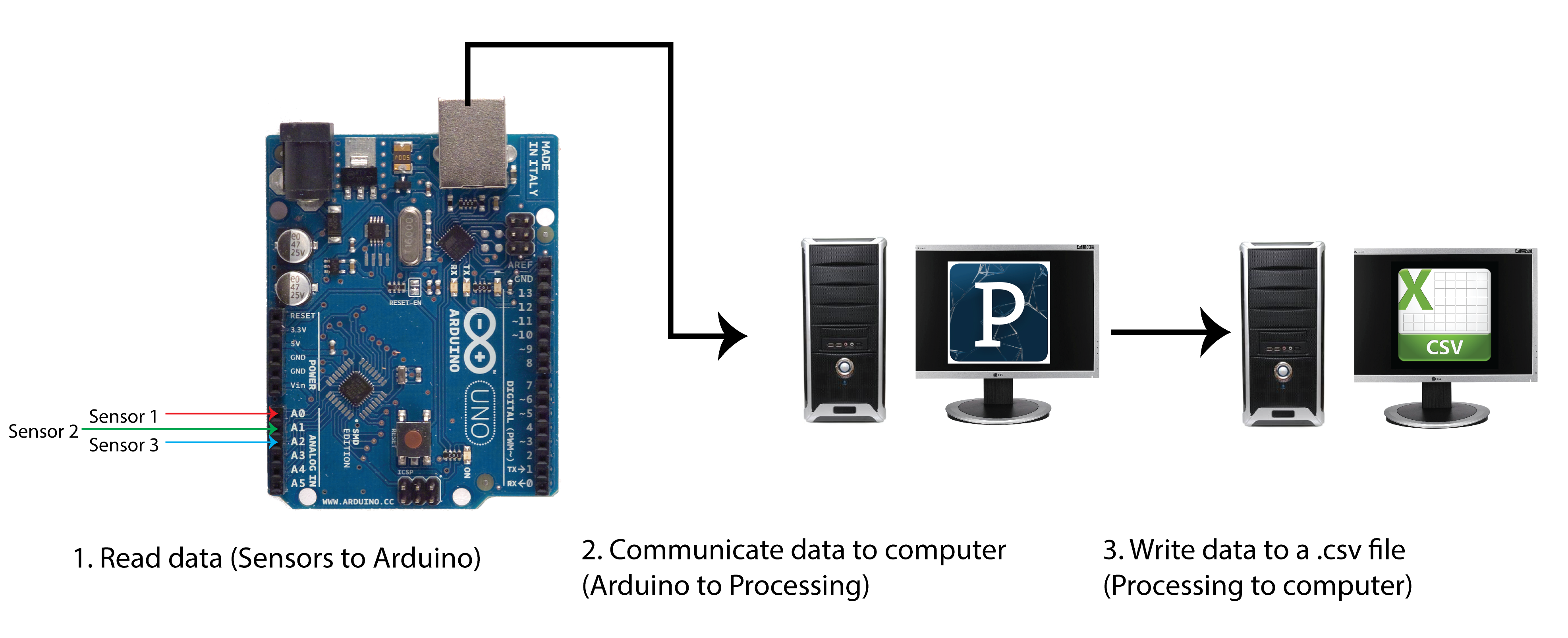
Here is an overview of what this tutorial accomplishes:
This is a beginning-level tutorial with one prerequisite! Arduino and Processing have to shake hands. I know it’s a lot to ask, but cooperation is at the root of any good spreadsheet. Here’s a link to a tutorial: http://www.hackerscapes.com/2014/10/lab-6-processing/
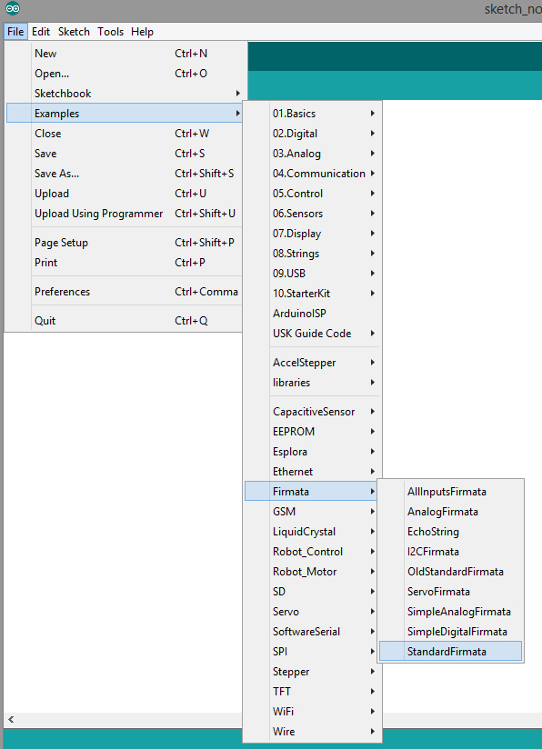
First, Download and Install the following:
- Arduino IDE: http://arduino.cc/en/main/software
- Processing 2.0: https://www.processing.org/download/
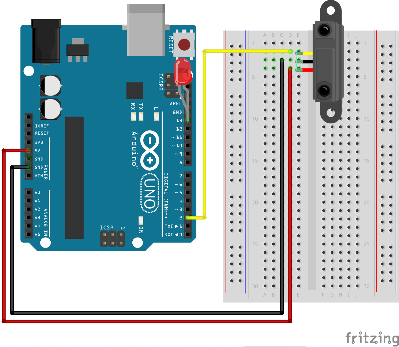
Step 1: Read Data, Send to Processing via Serial Port
First, set up the Arduino side. Here’s a a gist-y sketch:
|
1 2 3 4 5 6 7 8 9 10 11 12 13 14 15 16 17 18 19 20 21 22 23 24 25 26 27 28 29 30 31 32 33 34 35 36 37 38 39 40 41 42 43 44 45 46 47 48 49 50 51 52 53 54 55 56 57 58 59 60 61 62 63 64 65 66 67 68 69 70 71 72 73 74 |
/* Sending Data to Processing via the Serial Port This sketch provides a basic framework to send data from Arduino to Processing over a Serial Port. This is a beginning level sketch. Hardware: * Sensors connected to Arduino input pins * Arduino connected to computer via USB cord Software: *Arduino programmer *Processing (download the Processing software here: https://www.processing.org/download/ Additional Libraries: *Read about the Software Serial library here: http://arduino.cc/en/Reference/softwareSerial Created 12 November 2014 By Elaine Laguerta http://url/of/online/tutorial.cc */ /*To avoid overloading the Arduino memory, and to encourage portability to smaller microprocessors, this sketch does not timestamp or transform data. In this tutorial, timestamping data is handled on the processing side. Whether you process data on the Arduino side is up to you. Given memory limitations of the Arduino, even a few computations and mapping of values can max out the memory and fail. I recommend doing as little as possible on the Arduino board.*/ #include SoftwareSerial.h /*Declare your sensor pins as variables. I'm using Analog In pins 0 and 1. Change the names and numbers as needed Pro tip: If you're pressed for memory, use #define to declare your sensor pins without using any memory. Just be careful that your pin name shows up NOWHERE ELSE in your sketch! for more info, see: http://arduino.cc/en/Reference/Define */ int sensor1Pin = 0; int sensor2Pin = 1; int sennsor3Pin = 2; /*Create an array to store sensor values. I'm using floats. Floats use 4 bytes to represent numbers in exponential notation. Use int if you are representing whole numbers from -32,768 to 32,767. For more info on the appropriate data type for your sensor values, check out the language reference on data type: http://arduino.cc/en/Reference/HomePage Customize the array's size to be equal to your number of sensors. */ float sensorVals[] = {0,0,0} /*Pro tip: if you have a larger number of sensors, you can use a for loop to initialize your sensor value array. Here's sample code (assuming you have 6 sensor values): float sensorVals[6]; int i; for (i=0; i<6; i++) { sensorVals[i] = 0; } */ void setup(){ Serial.begin(9600); //This line tells the Serial port to begin communicating at 9600 bauds } // void loop(){ //read each sensor value. We are assuming analog values. Customize as nessary to read all of your sensor values into the array. Remember to replace "sensor1Pin" and "sensor2Pin" with your actual pin names from above! sensorVal[0] = analogRead(sensor1Pin); sensorVal[1] = analogRead(sensor2Pin); sensorVal[2] = analogRead(sensor3Pin); /*If you are reading digital values, use digitalRead() instead. Here's an example: sensorVal[0] = digitalRead(sensor1Pin); */ //print over the serial line to send to Processing. To work with the processisng sketch we provide, follow this easy convention: separate each sensor value with a comma, and separate each cycle of loop with a newline character. //Remember to separate each sensor value with a comma. Print every value and comma using Serial.print(), except the last sensor value. For the last sensor value, use Serial.println() Serial.print(sensors[0]); Serial.print(","); Serial.print(sensors[1]); Serial.print(","); Serial.println(sensors[1]); delay(100); } |
Step 2: Use Processing to Receive Data from Arduino, Write data to a Table, and Save Table to a .csv
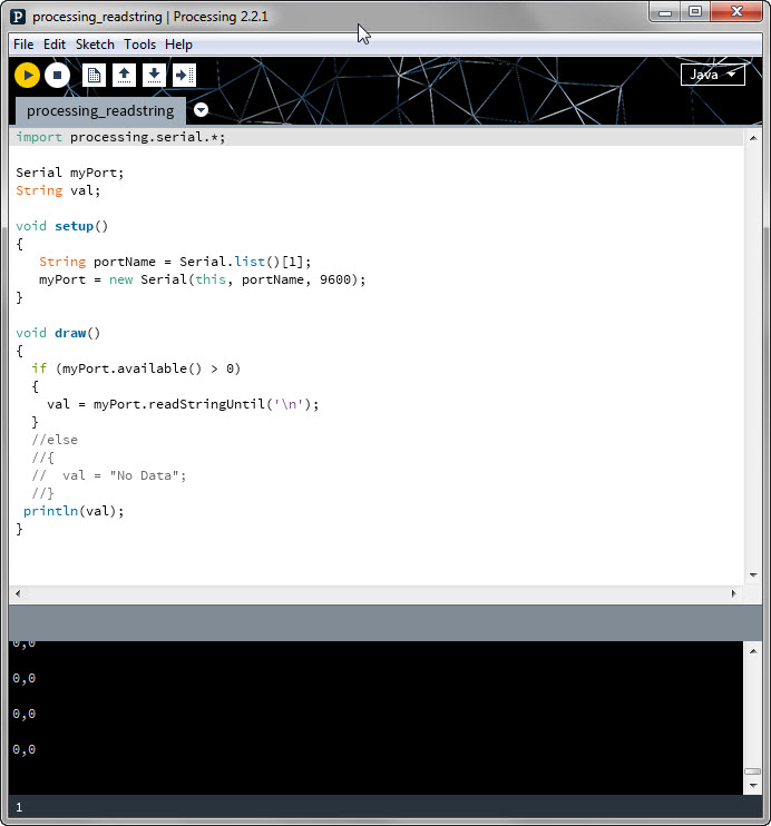
Now we will handle the processing side.
|
1 2 3 4 5 6 7 8 9 10 11 12 13 14 15 16 17 18 19 20 21 22 23 24 25 26 27 28 29 30 31 32 33 34 35 36 37 38 39 40 41 42 43 44 45 46 47 48 49 50 51 52 53 54 55 56 57 58 59 60 61 62 63 64 65 66 67 68 69 70 71 72 73 74 75 76 77 78 79 80 81 82 83 84 85 86 87 88 89 90 91 92 93 94 95 |
/* Saving Values from Arduino to a .csv File Using Processing - Pseduocode This sketch provides a basic framework to read data from Arduino over the serial port and save it to .csv file on your computer. The .csv file will be saved in the same folder as your Processing sketch. This sketch takes advantage of Processing 2.0's built-in Table class. This sketch assumes that values read by Arduino are separated by commas, and each Arduino reading is separated by a newline character. Each reading will have it's own row and timestamp in the resulting csv file. This sketch will write a new file a set number of times. Each file will contain all records from the beginning of the sketch's run. This sketch pseduo-code only. Comments will direct you to places where you should customize the code. This is a beginning level sketch. The hardware: * Sensors connected to Arduino input pins * Arduino connected to computer via USB cord The software: *Arduino programmer *Processing (download the Processing software here: https://www.processing.org/download/ *Download the Software Serial library from here: http://arduino.cc/en/Reference/softwareSerial Created 12 November 2014 By Elaine Laguerta http://url/of/online/tutorial.cc */ import processing.serial.*; Serial myPort; //creates a software serial port on which you will listen to Arduino Table dataTable; //table where we will read in and store values. You can name it something more creative! int numReadings = 500; //keeps track of how many readings you'd like to take before writing the file. int readingCounter = 0; //counts each reading to compare to numReadings. String fileName; void setup() { String portName = Serial.list()[1]; //CAUTION: your Arduino port number is probably different! Mine happened to be 1. Use a "handshake" sketch to figure out and test which port number your Arduino is talking on. A "handshake" establishes that Arduino and Processing are listening/talking on the same port. //Here's a link to a basic handshake tutorial: https://processing.org/tutorials/overview/ myPort = new Serial(this, portName, 9600); //set up your port to listen to the serial port table.addColumn("id"); //This column stores a unique identifier for each record. We will just count up from 0 - so your first reading will be ID 0, your second will be ID 1, etc. //the following adds columns for time. You can also add milliseconds. See the Time/Date functions for Processing: https://www.processing.org/reference/ table.addColumn("year"); table.addColumn("month"); table.addColumn("day"); table.addColumn("hour"); table.addColumn("minute"); table.addColumn("second"); //the following are dummy columns for each data value. Add as many columns as you have data values. Customize the names as needed. Make sure they are in the same order as the order that Arduino is sending them! table.addColumn("sensor1"); table.addColumn("sensor2"); } void serialEvent(Serial myPort){ val = myPort.readStringUntil('\n'); //The newline separator separates each Arduino loop. We will parse the data by each newline separator. if (val!= null) { //We have a reading! Record it. val = trim(val); //gets rid of any whitespace or Unicode nonbreakable space println(val); //Optional, useful for debugging. If you see this, you know data is being sent. Delete if you like. float sensorVals[] = float(split(val, ',')); //parses the packet from Arduino and places the valeus into the sensorVals array. I am assuming floats. Change the data type to match the datatype coming from Arduino. TableRow newRow = dataTable.addRow(); //add a row for this new reading newRow.setInt("id", table.lastRowIndex());//record a unique identifier (the row's index) //record time stamp newRow.setInt("year", year()); newRow.setInt("month", month()); newRow.setInt("day", day()); newRow.setInt("hour", hour()); newRow.setInt("minute", minute()); newRow.setInt("second", second()); //record sensor information. Customize the names so they match your sensor column names. newRow.setFloat("sensor1", sensorVals[0]); newRow.setFloat("sensor2", sensorVals[1]); readingCounter++; //optional, use if you'd like to write your file every numReadings reading cycles //saves the table as a csv in the same folder as the sketch every numReadings. if (readingCounter % numReadings ==0)//The % is a modulus, a math operator that signifies remainder after division. The if statement checks if readingCounter is a multiple of numReadings (the remainder of readingCounter/numReadings is 0) { fileName = str(year()) + str(month()) + str(day()) + str(dataTable.lastRowIndex()); //this filename is of the form year+month+day+readingCounter saveTable(dataTable, fileName); //Woo! save it to your computer. It is ready for all your spreadsheet dreams. } } } void draw() { //visualize your sensor data in real time here! In the future we hope to add some cool and useful graphic displays that can be tuned to different ranges of values. } |
Additional Resources
- All about Tables in Processing: https://www.processing.org/reference/Table.html
- The Arduino Software Serial Library: http://arduino.cc/en/Reference/softwareSerial
- Arduino data types (a must-read before you choose the data type for your data input): http://arduino.cc/en/Reference/HomePage

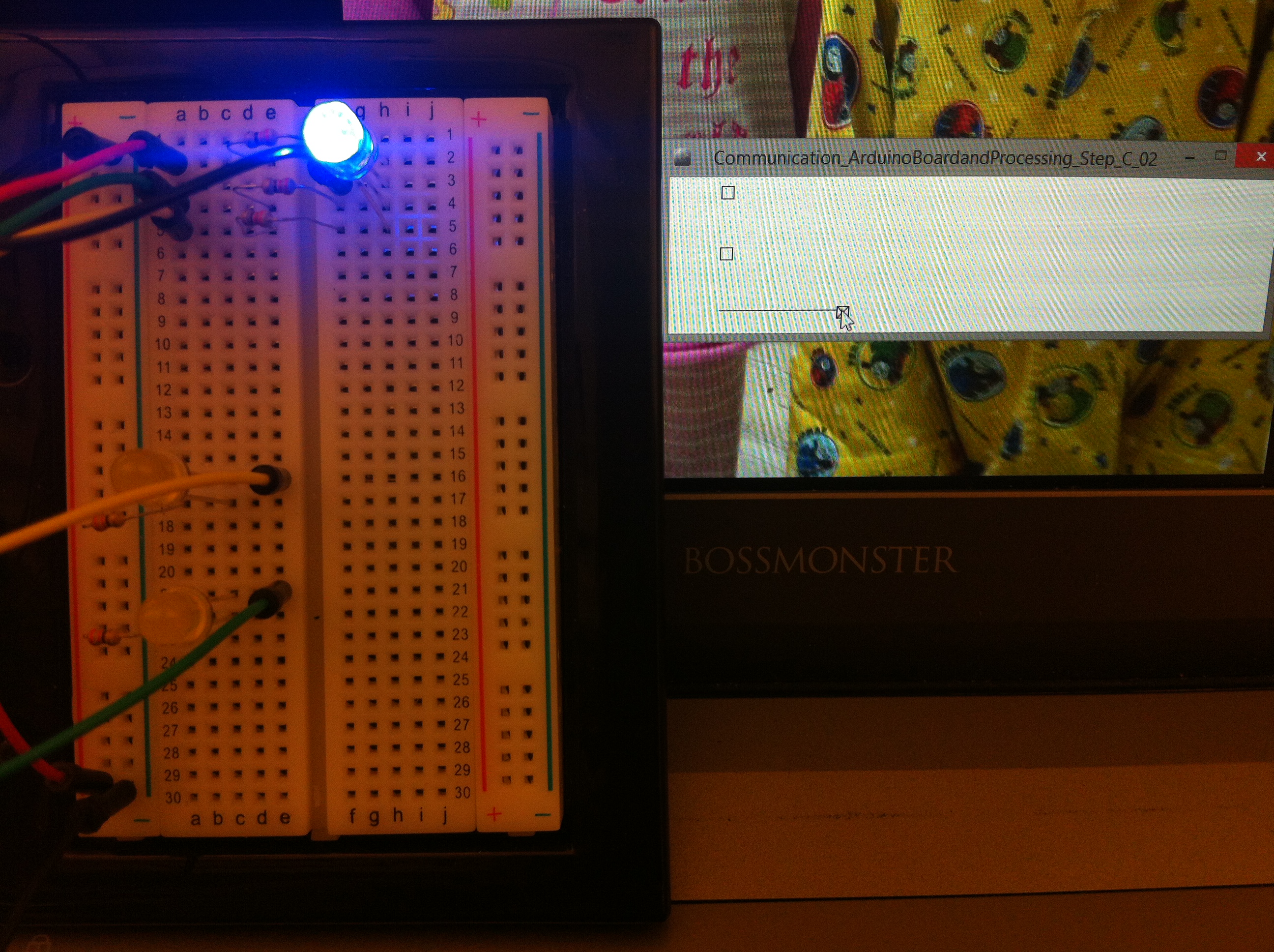
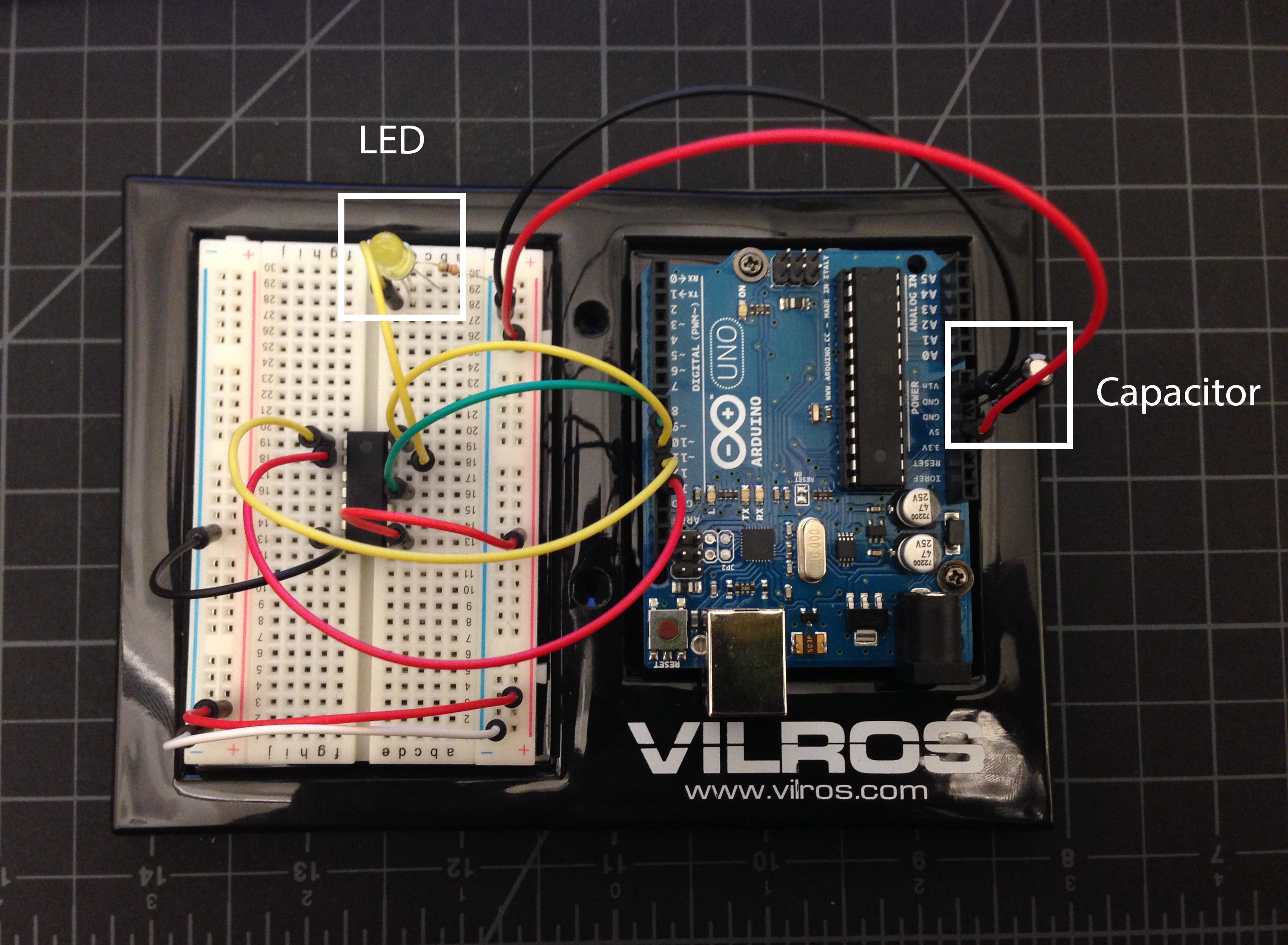
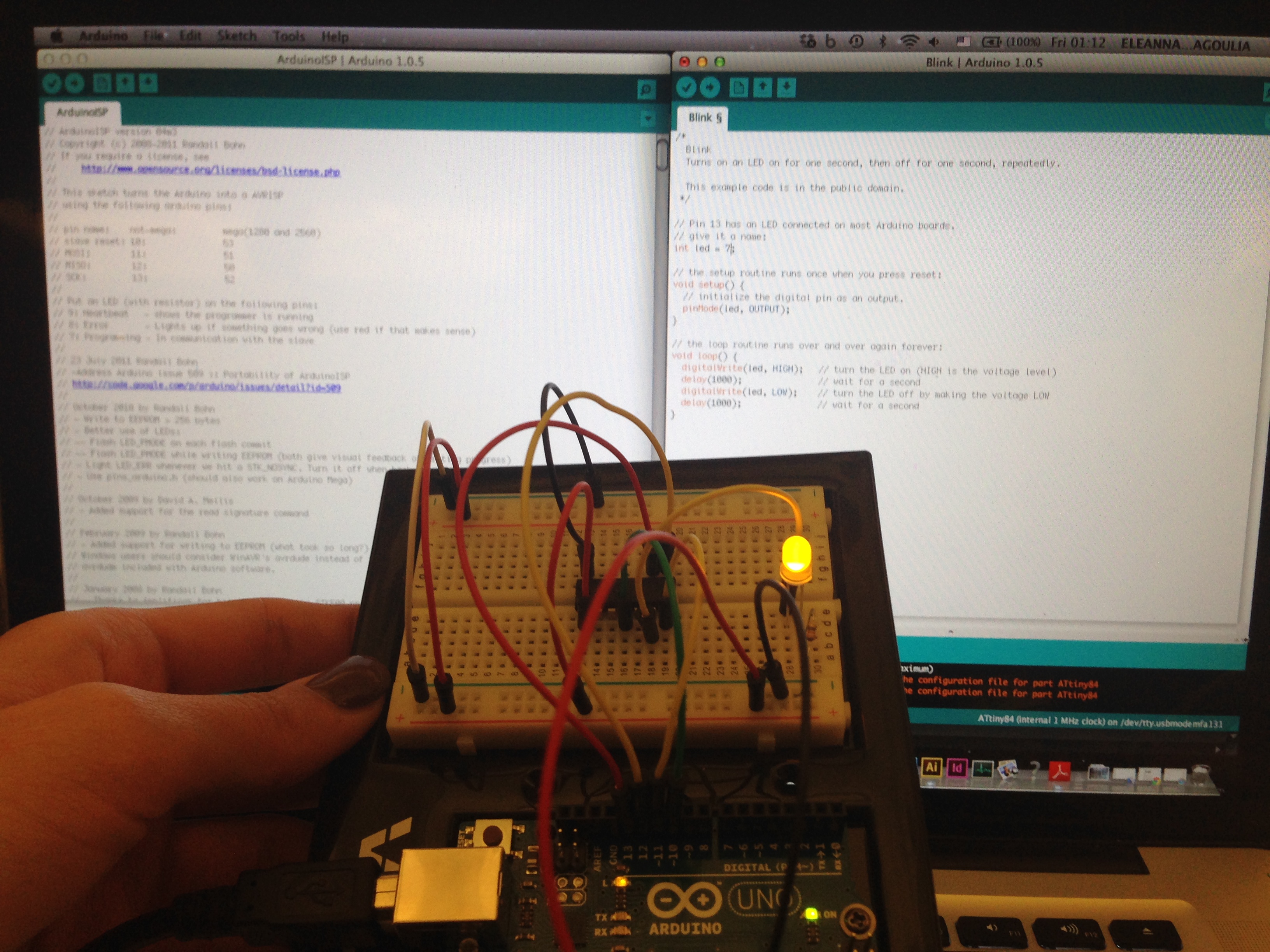
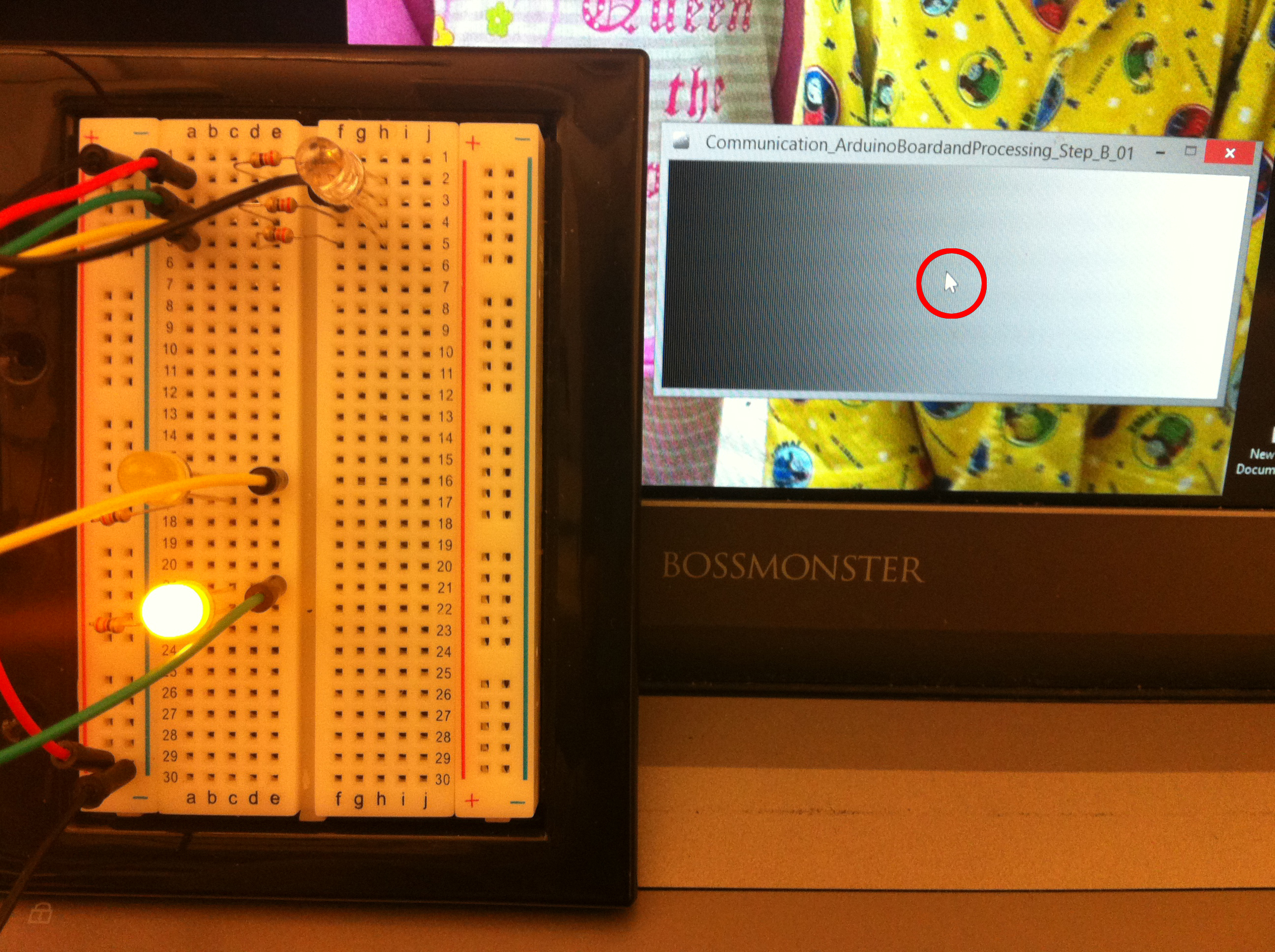
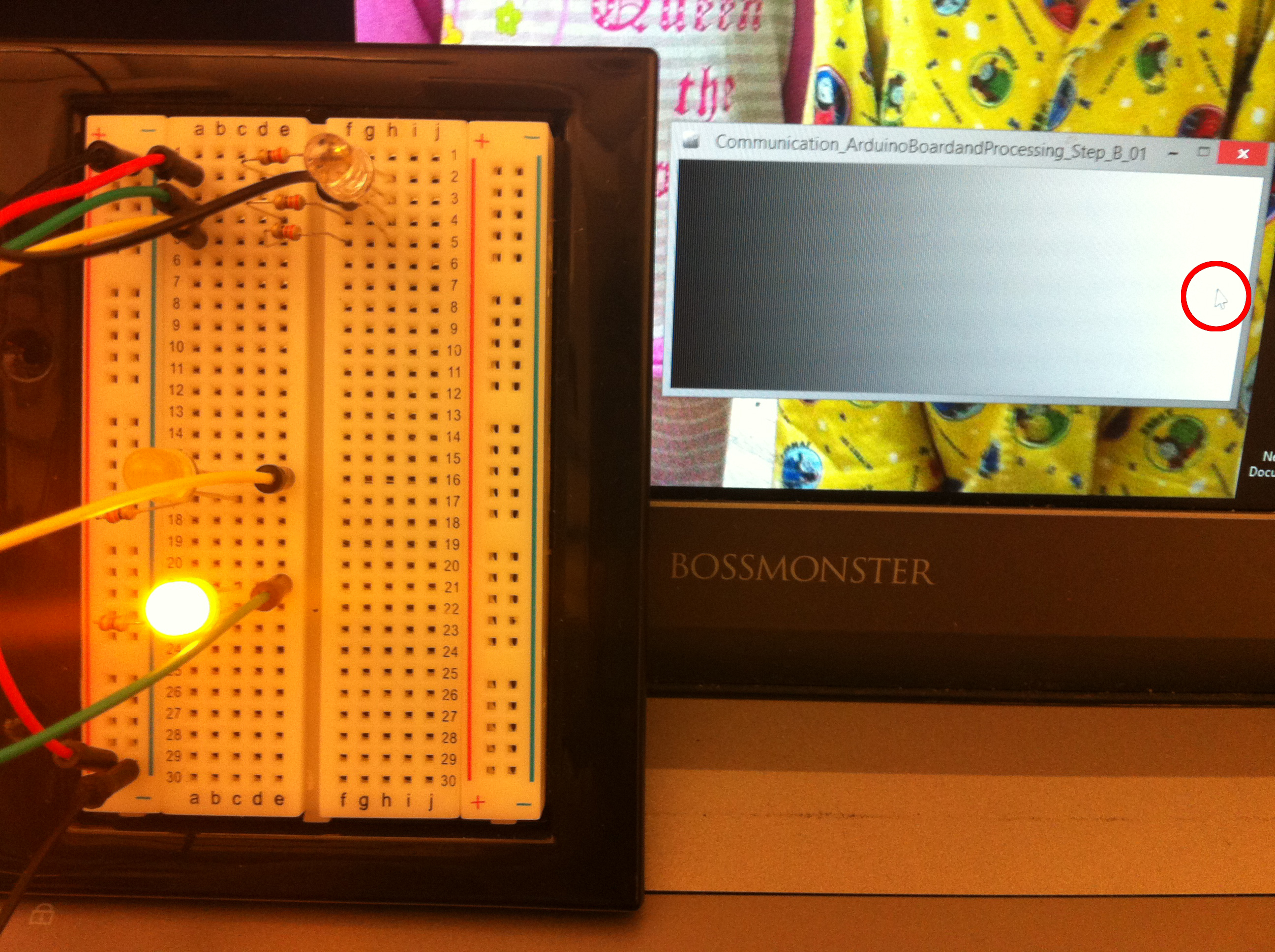
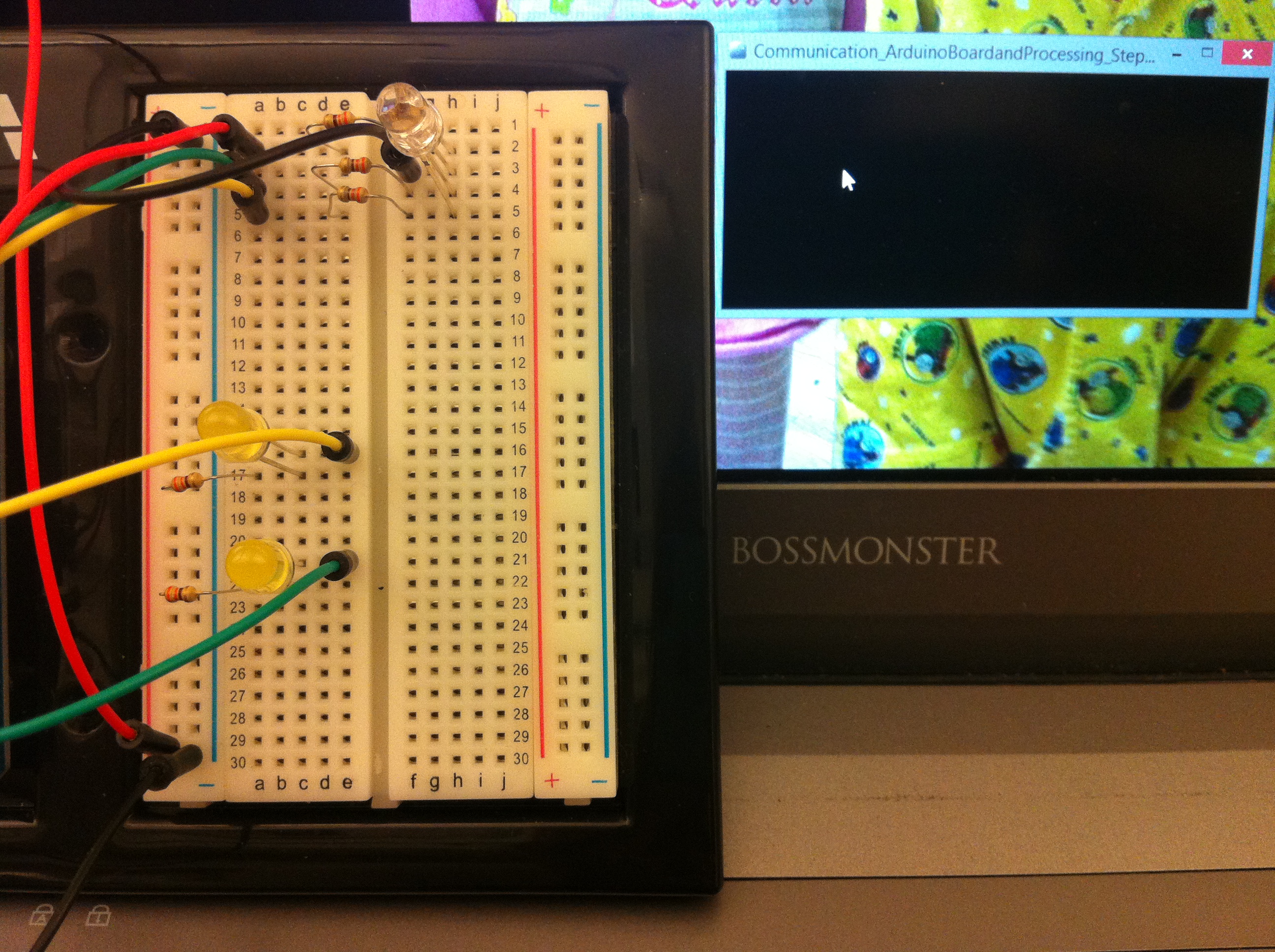 Click on the Processing sketch to blink an LED
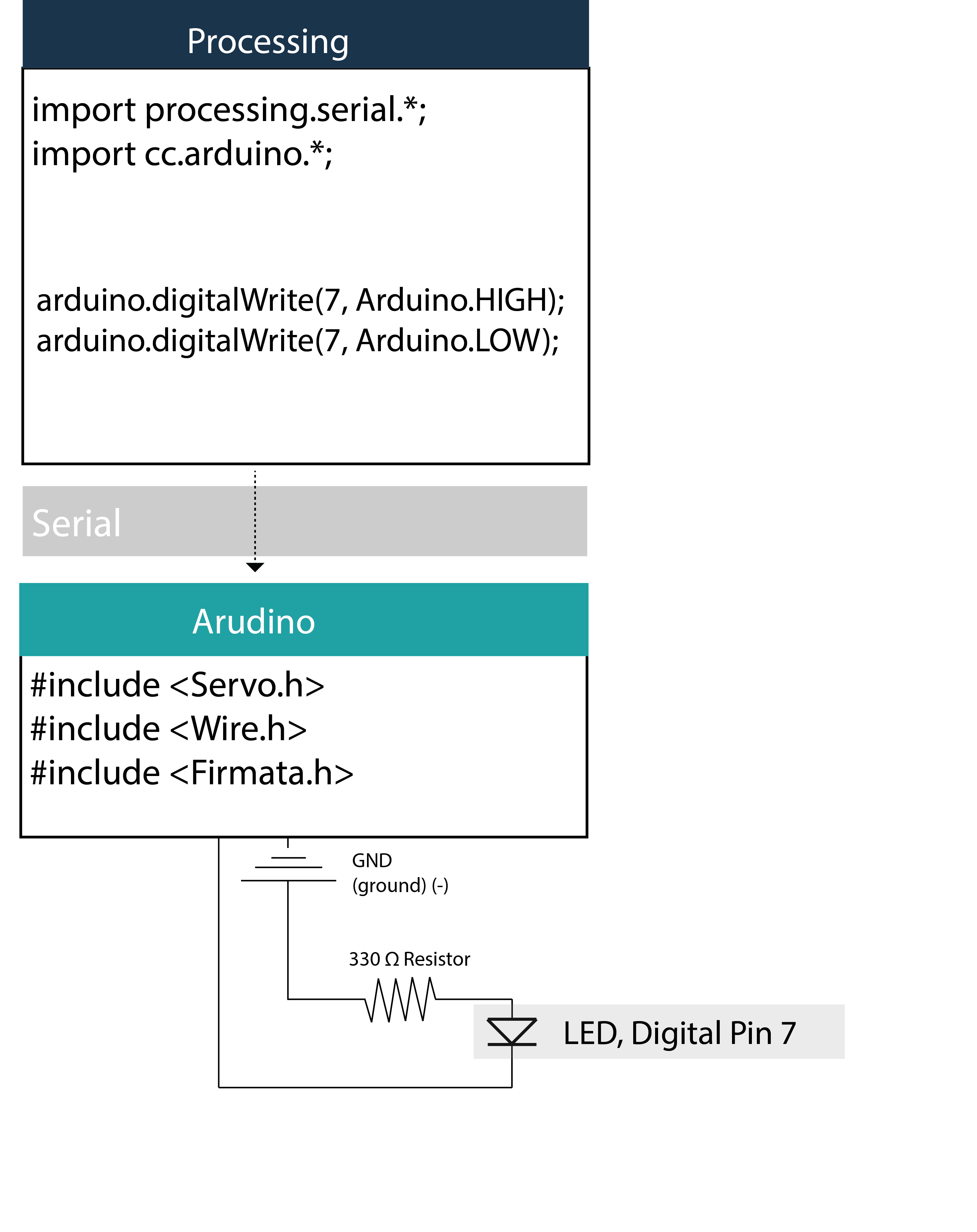
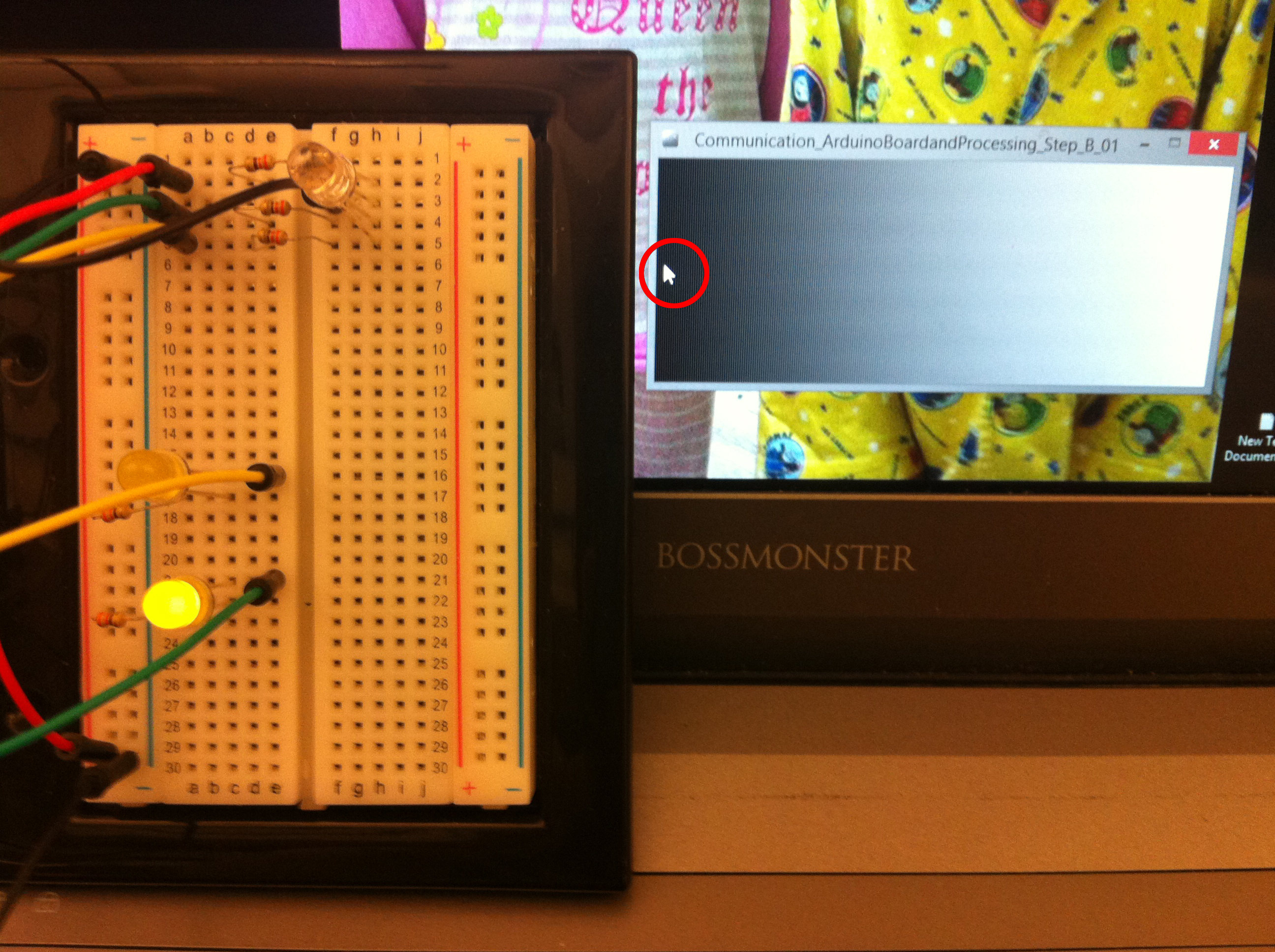


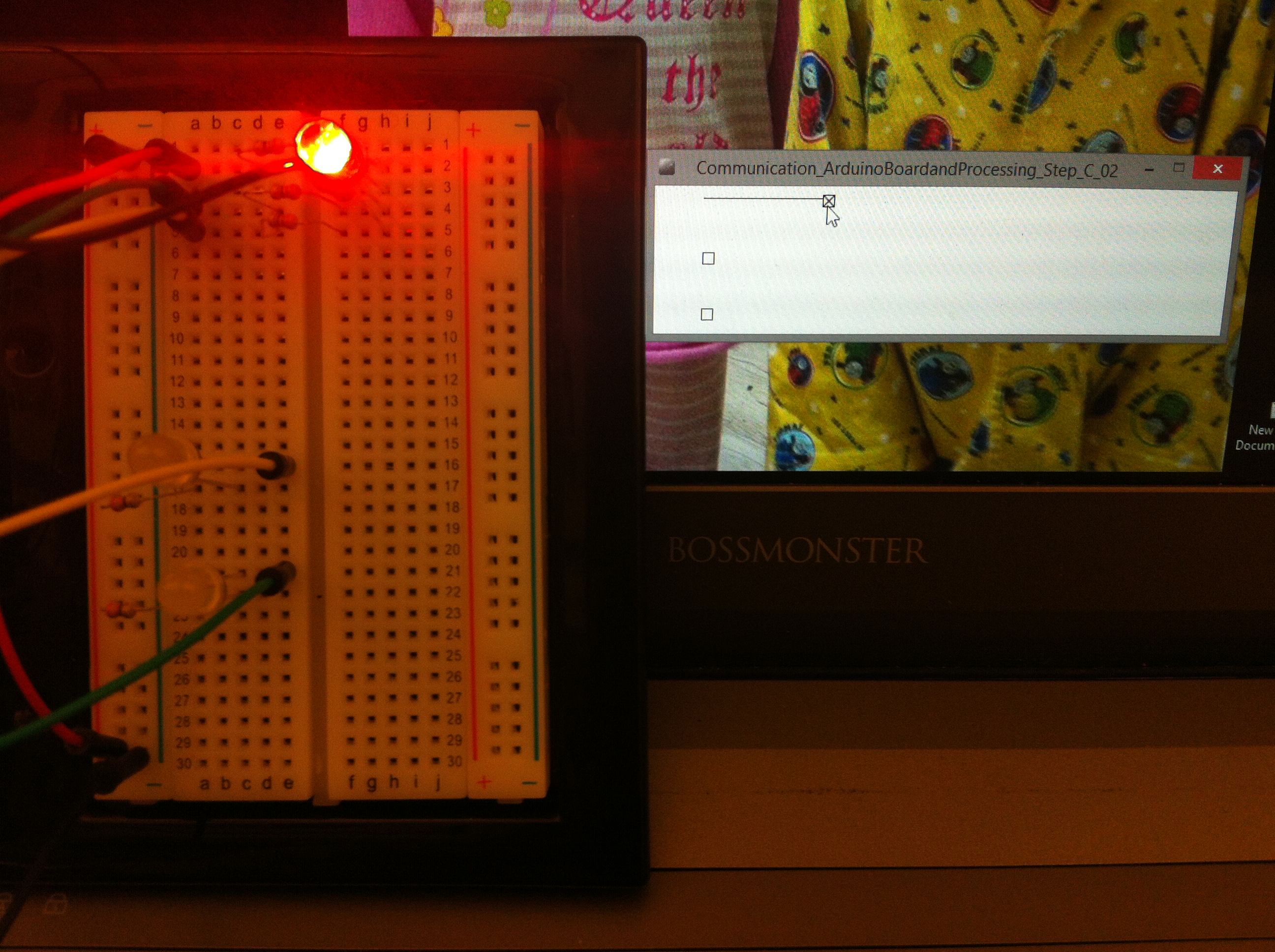
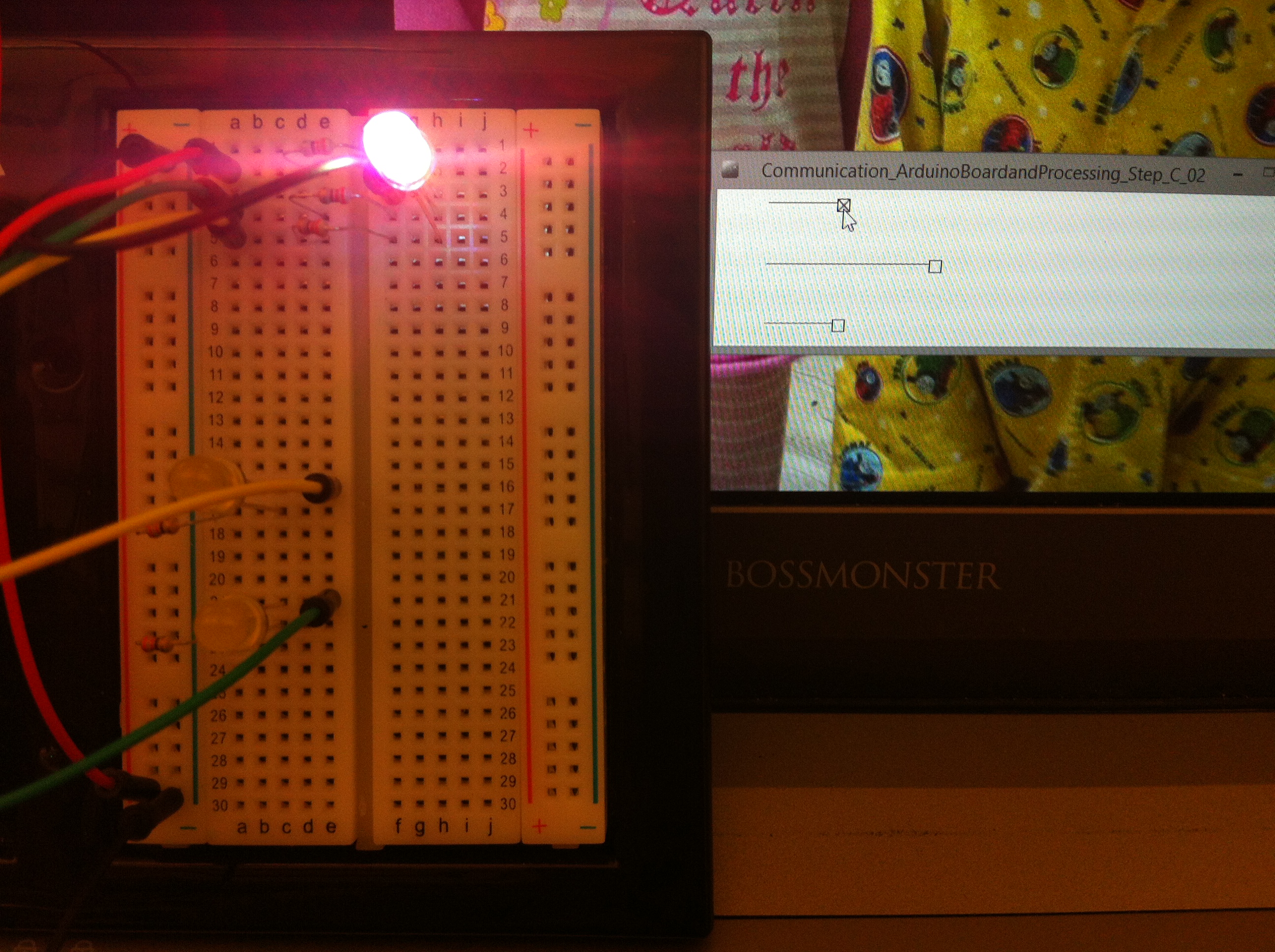
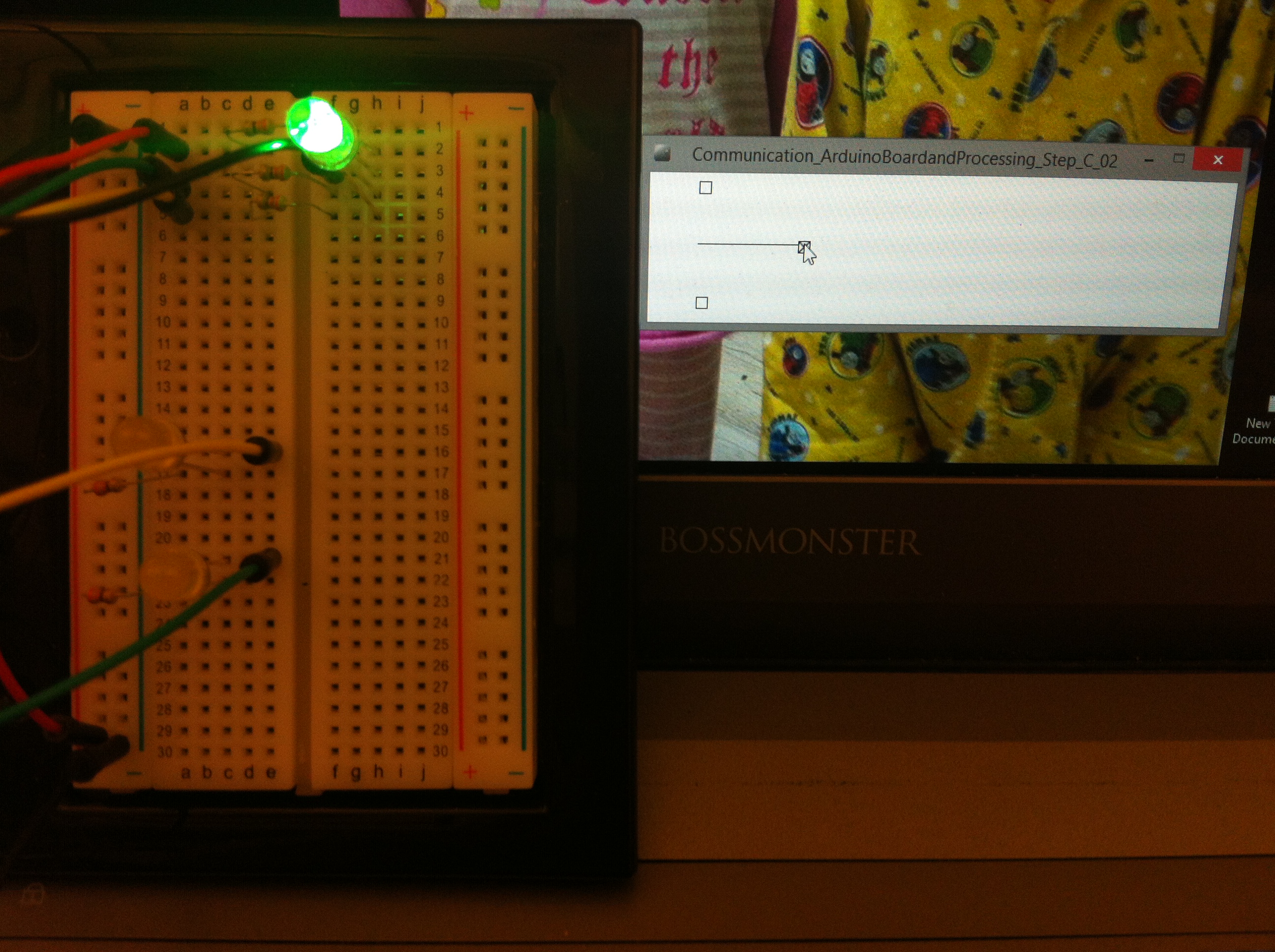 Changing RGB LED brightness with analogWrite function based on handle, value = green