In Class: Capacitive Touch Sensing

In this exercise, you are going to install an Arduino library, and then use it for capacitive (touch) sensing. First you will create two sensors, and then you will add a buzzer to your Arduino to make a tiny piano.

0. If you have the Arduino IDE open, close it.

1. Download the CapSense Library (called CapacitiveSensor04.zip) and save it somewhere that you can find it again. Unzip it. Open up the subfolder called “libraries.”

2. Inside libraries, you will see the CapacitiveSensor folder. Copy this folder into your Arduino Library folder. For me, the Arduino Library folder is located at My Documents > Arduino > Libraries. Yours should be similar.

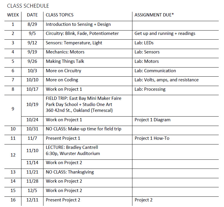
3. Launch the Arduino IDE. Now you should see the CapacitiveSensor library under your list of available libraries.

capsense_library_contributed

4. Take a minute to appreciate that you just installed your first library. There are gazillions of libraries out there. Now you have significantly more coding power than you did before.

5. Now go to File > Examples > CapacitiveSensor > CapacitiveSensorSketch. This is the sketch that you’ll be using.

6. Go back to take a look at the CapacitiveSensing page. Note that you can read about all of the methods that are included in the library, the variables that you need to send them, and the variables that they return. (Side note: methods are a lot like functions — you can use these words interchangeably with most everyone except coding purists.)

7.  CapacitiveSensorSketch creates 3 sensors. You are just going to make 2 sensors. Comment out every line that refers to cs_4_2. Also, since cs_4_2 is used to calculated total1, so you should also comment out any line that refers to total1.

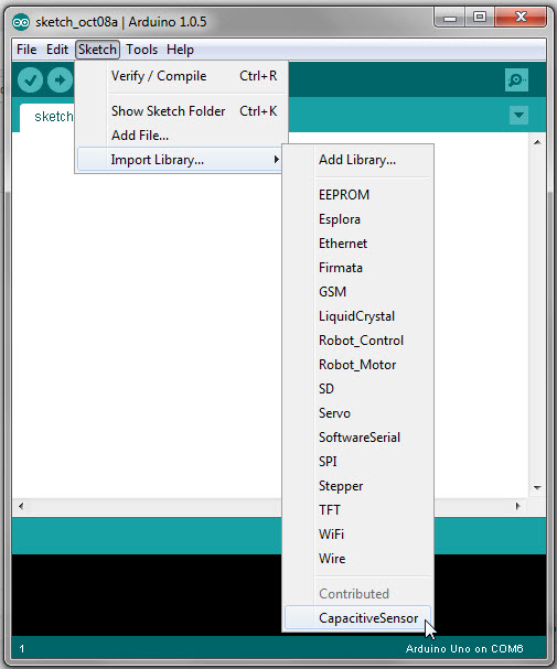
8. Set up your board using pins 4, 6 and 8.  Be sure to include a 10K ohm resistor on each sensor. Also, ground your board.

There is no single correct way to do this, but this is how I set it up (the resistors are between the positive rail and the green wires):

cap_sense_setup

9. Upload your CapacitiveSensorSketch.  Open the serial monitor. Click on the sensors, see what happens.

10. Try replacing the ends of the sensors (dimes in the example above) with something else that’s more or less conductive. How does it work? Do your values change?

11. Now, think about incorporating an output into your Arduino sketch so you can respond to a sensed touch. How would you make the piezo buzzer sound a single note when the left sensor is pressed?

12. After you have the left sensor worked out, add another note when the right sensor is pressed.

13. Add a third note for when both are pressed at the same time.

14. Manipulate the delay times and the buzz duration so the notes are as smooth as possible.

15. Now you have a tiny piano! Think about how you might add more keys.

Project Overview

In your classes, studios and daily lives, you encounter problems and challenges in the urban and suburban environment. Your project will respond to one of these problems or challenges by creating an electronic (e.g., Arduino) intervention in the public realm. This intervention will include both sensing and response.

You will work in teams of 3-4 people. Ideally, your team will have common interests, but diverse skills. The perfect team would include one person with a strong design vision, one person who likes to code, and one person who is interested in the circuitry. In reality, everyone has some of each of these characteristics, but consider all of these needs as you build your team. We will finalize teams in class on October 17.

Scaling up to work in the public realm will require some leaps. So far, you have primarily worked on small, desktop-sized projects. To gradually go larger, you will complete your final project in two phases. On the syllabus, this is called Project 1 and Project 2.

Following is a brief sketch of the remaining assignments in the class. I will post more on each assignment as the due date nears.

Phase 1

In the first phase, you will develop your project concept, and then dive into the details to ensure your concept is feasible.

  • You will create an elevator pitch for your project. What is a problem that you see in the urban environment? How does your project address this problem?
  • You will diagram your project. Where will the project be located? What are you sensing? How are you responding? Include a preliminary equipment list with costs.
  • Divide up your project. Think of the different connections and questions that need to be answered in order to build your project. Each person in your team will work on one piece of the overall design. (For example: how can you drive and power four servos simultaneously? how can you collect data from an anemometer?)
  • Each person in your team will write a blog post on this site (I will give you permissions to publish here as the time draws nearer). It will be a tutorial on how to execute your piece of the project. It will include a circuit diagram, code, and any other information you need to make your tutorial as clear as possible (e.g., text, images, or a brief video).
  • Your team will present your project concept to the class. Professor Louise Mozingo will join us. You will talk to us about the design and technical questions your team is wresting with. We will give you constructive feedback on how to advance your project.


Phase 2

Some people will find that, after exploring the details, their concept is not working. That is OK. At this point, everyone should take a step back and think about how their project should evolve, based on your new technical knowledge and design considerations.  You may choose to do a major project revision.

This revised project is the project you will execute for the rest of the semester. As you move through execution, iteratively consider:

  • How will we manage costs (i.e., complete the project within budget)?
  • How will we power the project?
  • How will we protect/enclose the project?

On December 11 (10a – 1p), you will present the problem your project responds to, what your project does, and how you do it. Your audience will be the class, Professor Mozingo, Professor Kyle Steinfeld (Architecture), and Andrea Gaffney (Gehl Studio/LAEP Lecturer). Depending on your concept, the project may be at full scale, or may be a model. Regardless, it will be a prototype of an urban solution.

Lab 5: More on circuits

In this lab, you’re going to learn more about circuits. First, you’re going to use a relay — an electrical switch — that allows you to turn on and off parts of your circuit. Then, you’re going to practice calculating resistance. Finally, you’re going to diagram your circuit.

1. Complete Circuit 11, Relays, in your Vilros Ultimate Starter Guide.  If your relay doesn’t work, check all your wires. Trace the circuitry and think about how the current is flowing. Look at the axon drawing to see how the relay should be oriented. If that still doesn’t work, flip the orientation of the diode (for me, I needed the dark side of the diode on the right).

2. Make your circuit a little more exciting. On one side of the switch, run 2 LEDs in series. One the other side, run 2 LEDs in parallel. When each side is activated, write to your serial monitor: “Parallel On” or “Series On.”

3. What resistors do you need for your circuit, according to Ohm’s Law?  You’ll need to calculate this separately for each side of the switch. Show me your math. Make sure your circuit uses the most appropriate resistors. (4 points)

4. Take a short video of your circuit in action. Be sure to show the wiring well enough that I can actually see one side is wired in series and one in parallel. Also, be sure to show the serial monitor. In your video, feel free to talk and point to things.  (8 points)

5. Draw a circuit diagram for your new circuit. Label everything, just as it’s done in the circuit diagram in your starter guide. (6 points)

Note that there are several different ways to go about drawing a circuit. This software, Fritzing, seems to be popular in the Arduino community. There are many other options available — just search around. You can even use a pen and paper (and a scanner). Whatever you use, make sure your circuit is clear.

6. Read about the why your resistors are colored as they are.

7. Read about how to destroy an Arduino. This link is a little strange because it’s an advertisement for an Arduino spin-off called a “Ruggeduino” that can supposedly withstand all the things you can do to kill your Arduino. But, it’s also a clear list. (If you think your circuit diagram was complicated, check out the ones they show on this page.)

8. If you’d like to read more about the basics, check out this primer on voltage, current and resistance at Sparkfun. It also includes links to tutorials on electricity and circuitry.

9. Or, check out this one on Adafruit. Start here and then keep clicking through to read “Revisiting Resistors,” “Revisiting Volts,” and “What to Adjust?”.

10. As always, post your assignment on bSpace.

Lab 4: Communicating

In this lab, you’ll explore serial communication by talking with Processing, the programming language and development environment that provided the original inspiration for the Arduino IDE. Processing is a very useful partner for Arduino — you’ll use it again in a few weeks.

1. Download Processing. If you need to look up any of the commands you’re using in Processing, check the Library and Reference sections.

2. Do this tutorial from Sparkfun. Please type in each line of code yourself, rather than copying and pasting the code. Doing so will help you understand the code much more deeply. It will also make you aware of your typos, which will help you learn to write less buggy code.

A few things to watch out for in this tutorial:

The first chunk of Processing code that begins with “String portName = …” should be inside of the setup() function, which is not said very clearly.

When setting your port, try [0] for Macs, as the tutorial suggests. For Windows, try [1].  You’ll know you’re accessing the wrong port if you get an error. Once you figure out which number to use, use the same number every time you need to access the port in the code (at one point in the sample code, the value inexplicably changes to [4] — you should not do that).

Be sure to load your Arduino sketch, and then run your Processing sketch. If you run Processing first, you’ll get an error that says your serial port is busy.

For the lucky ones, connecting Processing to your serial port will be a breeze. For those of you with grouchy computers, this might be a pain. The issue is that a serial port cannot be accessed by two programs simultaneously. If you’re being told that the serial port is busy, even though you’re sure you uploaded Arduino first and then ran Processing second, it likely means that whatever program was last using the serial port did not properly close the port, locking you out. To fix this, you’ll have to reboot your computer. (Or use a program like Terminal or PuTTY, but rebooting is probably simpler if you’re not already familiar with those programs.) Also, be aware that if you’re using serial communication somewhere else (e.g., some other device plugged into your computer), that other device can occupy your serial port.

When you’re done, spend a little time reflecting on how you could incorporate sensor data into your sketch, in lieu of “Hello, world!”

3. Submit a video of your final project, when both sides are “shaking hands” (14 points).

4. In your Arduino code you saw a while loop. What is a while loop and how does it differ from a for loop? Thinking back on past sketches, when did you use a for loop? (2 points)

5. In the final code, when you click the mouse, the light turns on. When you click again, the light turns off. How does this differ from your first mouse-clicking/light-blinking sketch? Where do you see this difference manifest in the code? (4 points)

6. Please submit your video and answers to the questions on bSpace under Lab 4.

Lab 3: Motors

In this lab, you will work with motors.  First, you will practice using servo and DC motors. Then, you will make one of your motors respond to a sensed stimulus. Lastly, you will learn more about powering motors.

1. Complete Circuit 8 in your Vilros Ultimate Starter Kit Guide, “A Single Servo.” Alter the pattern of the motor from the default provided in the code. Take a short (<15 sec) video of your motor working. (3 points)

2. Complete Circuit 10, “Spinning a Motor.” Alter the pattern of the motor from the default provided in the code. Take a short (<15 sec) video of your motor working. (3 points)

3. Combine one of the sensors from Lab 2 with either motor. Make your motor turn in response to the sensor. Temporarily attach some sort of physical object to your motor, so the motor is actually moving something.

4. Write a short paragraph describing what your project does. Why did you choose to use the motor that you chose? Read about different motors. (2 points)

5. Submit your code. Be sure to include comments describing what each piece of the code does. (4 points)

6. Submit a short (<30 sec) video of the project. (2 points)

7. What is a transistor? Why did you use it for the DC motor? (2 points)

8. Search the internet a more powerful motor. Submit a link to this motor. What is the suggested voltage for your bigger motor? (2 points)

9. To power the bigger motor you chose, do you need a motor shield? What is a motor shield? (2 points)

10. Submit your questions + videos on bSpace under Assignments > Lab 3.

**Updated October 16, 2014 to correct typos/errors.

Lab 2: Sensors

In this lab you will work with four different sensors. You will sense touch (two different ways), then light intensity, then temperature. After, you’ll look around on the internet for other types of sensors — what sensors are you most interested in?

1. Follow the exercise for Circuit 2, Potentiometer, in your Vilros Ultimate Starter Kit Guide.

2. In a few sentences, describe how the potentiometer works. Why is the light intensity changing as you turn the knob? (2 points)

3. This is the first time you’ve used an Analog In pin. In a few sentences, describe the difference between the digital and analog pins. (2 points)

4. Follow the exercise for Circuit 5, Push Button.

5. In a few sentences, describe how the buttons work.  Why does the light go off when you depress both buttons? (2 points)

6. Take a quick (< 15 sec video) of Circuit 5, showing what happens as you push the buttons. (2 points)

7. Follow the exercise for Circuit 6, Photo Resistor.

8. In a couple sentences, describe how the photo resistor works. Is it more similar to the potentiometer or push buttons? (1 point)

9. Take a photograph of your completed Circuit 6. (2 points)

10. Follow the exercise for Circuit 7, Temperature.

11. Take a photo or screen grab of your serial monitor showing temperature readings. (2 points)

12. What is a serial monitor? (1 point)

13. Search the internet for more Arduino sensors. You may want to start by scrolling through this page. Find 2 sensors that you would be interested in using.

14. For each sensor, submit (6 points):

    • The name of the sensor
    • A link to where you can buy the sensor
    • A link to some sample code/tutorial that helps you figure out how to use the sensor.
    • What does the sensor do? (2-3 sentences)
    • In looking at the sample code, do you understand what’s going on? If you bought the sensor, what would you need to learn in order to get it going? (1 paragraph)

Note: finding sample code will take some digging around. You may want to start saving links to code that you find helpful. I use Evernote for this sort of stuff.

15. Post answers to the questions + videos on bSpace under Assignments > Lab 2. Be sure to hit the submit button.


Lab 1: LEDs

You’ll start this lab by reading about some basics of the Arduino board. Then you’ll dive into LEDs. You’ll use an RGB LED and you’ll look at the multiple LED sketch again (the same one we used in class). Finally, you’ll combine an RGB with multiple LEDs.

1. Get to know your Arduino better. Read the excerpt from Chapter 1 and 2 of Arduino for Dummies posted on bSpace under Resources.

2. Skim the the beginning of the instruction book that comes with your starter kit.

3. Download the code on www.vilros.com/uskcode, as described by the instruction book. (You have to register, but the good news is that they don’t seem to send spam email.)

4. Follow the exercise for Circuit 3, RGB LED. Look at the two function calls inside of void loop() — you’ll see mainColors() and showSpectrum().

Comment out (i.e., insert two forward slashes, //) before mainColors(). Upload the code again. How does the display change?

Replace showSpectrum() with showRGB(0).  What happens? Change the number inside the parentheses — what does showRGB(200) look like? showRGB(500)? showRGB(767)?

5. Revisit Circuit 4, Multiple LEDs. (Note: the Vilros code is identical to the code I provided on bSpace.) Carefully read the code, including all of the comments. Do you understand how it works? How can you change the pattern of the blinking lights?

6. Combine the RGB LED and at least two additional simple LEDs . Write a new sketch that makes the lights blink sequentially.  Any blinking pattern is fine. You may re-use code from the from the Circuit 3 and Circuit 4 examples.

7. Write a short paragraph stating what your project does. (3 pts)

8. Save your Arduino sketch. Be sure to annotate your code with comments, like you saw in both the RGB and Multiple LED sketches. What do the different pieces of your sketch do? (10 points)

9. Create a short (< 30 sec) video of your project. (7 points)

10. Please submit your work on bSpace under Assignments, Lab 1. You will turn in a total of 3 files, as described in steps 7, 8, and 9. Be sure to click the “submit” button when you are done uploading your work. After, you will receive a confirmation email from bSpace.

Resources

The sky’s the limit! Just like it is for this Arduino-equipped weather balloon. Source: http://maxdarham.com/images/IMG_0551_lightbox.jpg

As you start getting into Arduino, you may want to expand beyond the class.  Here’s some ideas on where to go.  Feel free to add to this list in the comments.

Learn:

Hack:

Shop:

Get inspired:

Getting Started

  1. Buy the Arduino Uno Ultimate Starter Kit ($55 on Amazon, or purchase elsewhere)
  2. Install the Arduino IDE (Arduino 1.0.5) on your laptop
  3. Read this short, prescient article written by Mark Weiser in 1996 on ubiquitous computing: Weiser_OpenHouse
  4. Reflect on lecture and the Weiser article. Is there value in a digital, electronically-enabled landscape? What opportunities do you see? What cautions? Be prepared to discuss in Week 2 (9/5).
  5. Bring your laptop to class on 9/5

Environmental Sensing and Responsive Design