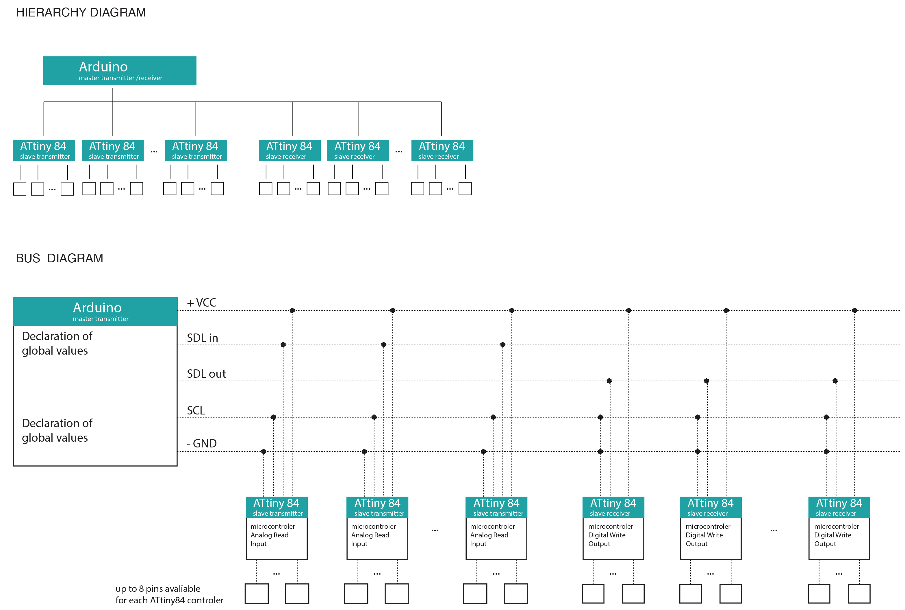
This tutorial describes the process of programming an ATtiny84 micro -controller through an Arduino board. The ATtiny84 is a high performance, small size processor that can be programmed and used instead of an Arduino board. This processor is similar to the original Arduino processor that is embedded on the Arduino Uno board. The use of a series of ATtinies 45/85 or 44/84 allows multiple connection of sensors or LEDs that exceed substantially the number of Pins that the Arduino Uno board provides. This means that instead of using multiple Arduinos to connect multiple sensors or output devices, we can use multiple ATtinies in order to save space, as well as money. In order to program a series of ATtinies and control the data flow from the Arduino board to them and vice versa, you will need to program each micro-controler individually through the breadboard and store the program to each. In the meantime, you will need to build a circuitry diagram called “bus diagram”, in order to understand the data flow between the Arduino and the multiple ATtinies. The structure of the “bus diagram” is relatively simple. It is a tree hierarchy diagram of Master and Slaves, which means that it does not include network connections between the controllers. The Arduino board is defined as the “Master” controller of the system and the ATtinies as the “Slave” micro-controlers. This means that the Arduino is controlling the flow of data exclusively, by “calling” each ATtiny at a time. Hence, every ATtiny “talks” directly to the Arduino board individually through the Arduino pins.
These diagrams explain the hierarchy of data flow, as well a typical structure of a “bus diagram”.
The following steps will describe the process of programming one ATtiny84 micro-controler through the breadboard.
For this process you will be required:
1_ Arduino Uno board
2_ Breadboard
3_ ATtiny84
4_ Capacitor 10uF
5_ 1 LED
6_ 1 resistor 330KΩ
7_ Jumper wires
Step 1
Open a new Arduino IDE (Arduino sketch window). If you don’t have Arduino installed, you can download it from the following link: http://arduino.cc/en/Main/Software
Step 2
In order to program an ATtiny84 you should import the ATtiny boards. To do so, download the ATtiny master zip. by clicking here: attiny-master
Consult the “Read me” file for accessing the necessary instructions. Unzip the “attiny – master” folder and paste the “attiny” folder in the Arduino sketchbook folder. Inside the Arduino sketchbook folder, create a sub-folder under the name “hardware” and paste the “attiny” folder there. Your “attiny” folder should contain a text file named “boards” and a folder named “variants“.
Step 3
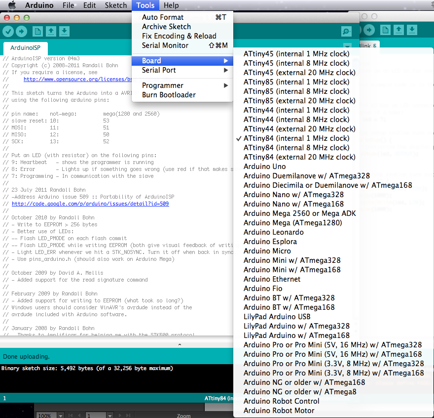
Reboot your Arduino IDE. If you go to the “Sketch” menu –> Boards drop down, you should be able to see the names of the new boards that you’ve just installed.
Step 4
After installing the ATtiny boards you can begin connecting the ATtiny with the Arduino board. You can connect the two through the breadboard.
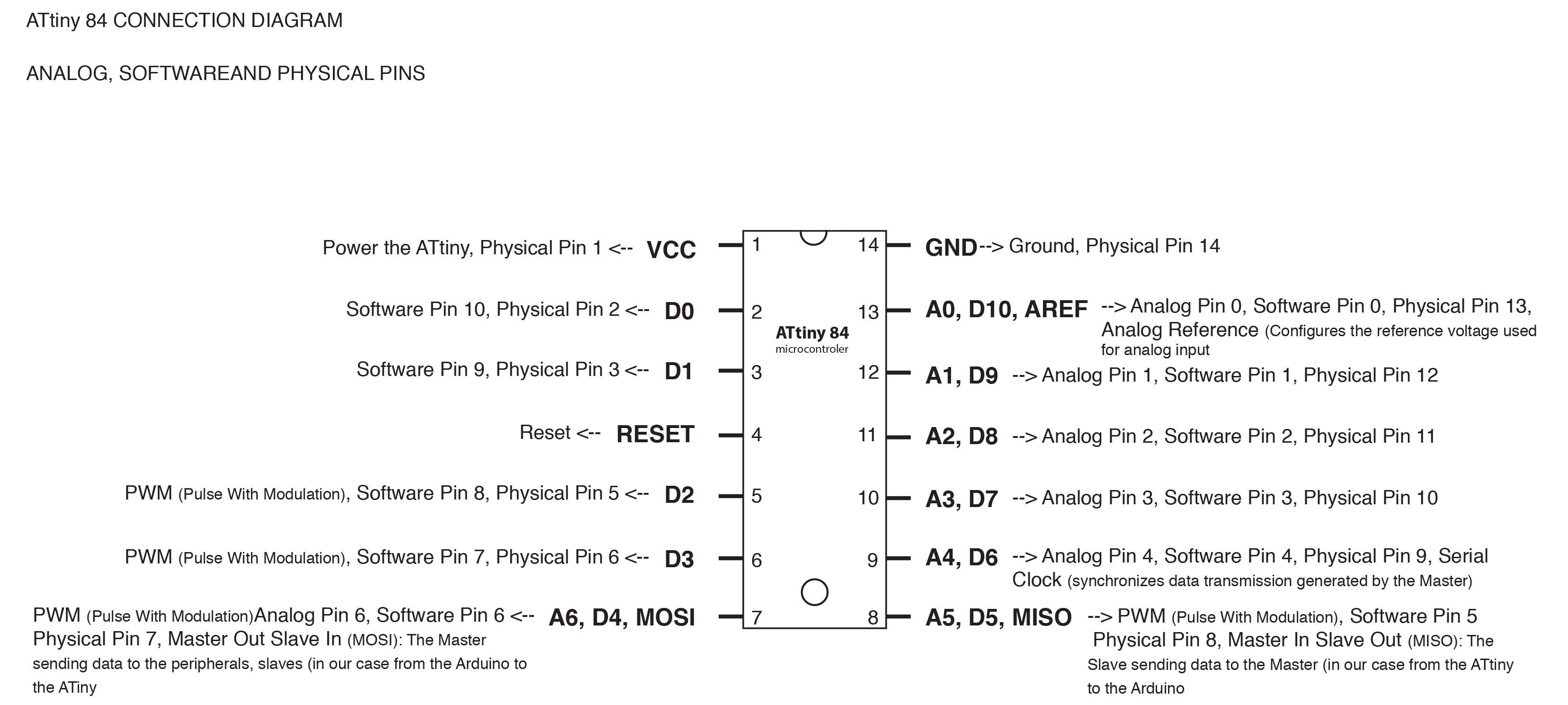
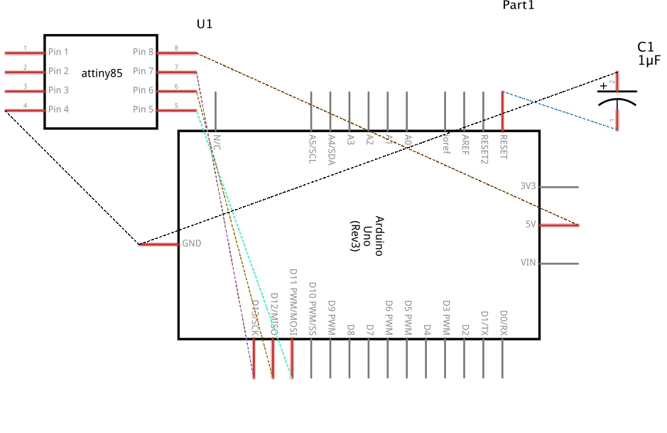
Before we start listing the connections, we should go through and describe the pins of the ATtiny. There are two kinds of configurations that describe the ATtiny pins, Physical and Software. The Physical Pins and the Pin numbers in the Software are very different. For example, on an ATtiny84, Physical Pin 1 is for VCC while, in the Software, Digital Pin 1 is actually Physical Pin 12. Also, the Analog Pins can have different numbers than the digital pins at the same physical location. The following diagram gathers all the different configurations of the ATtiny84 pins.
ATtiny 84 Pin Diagram
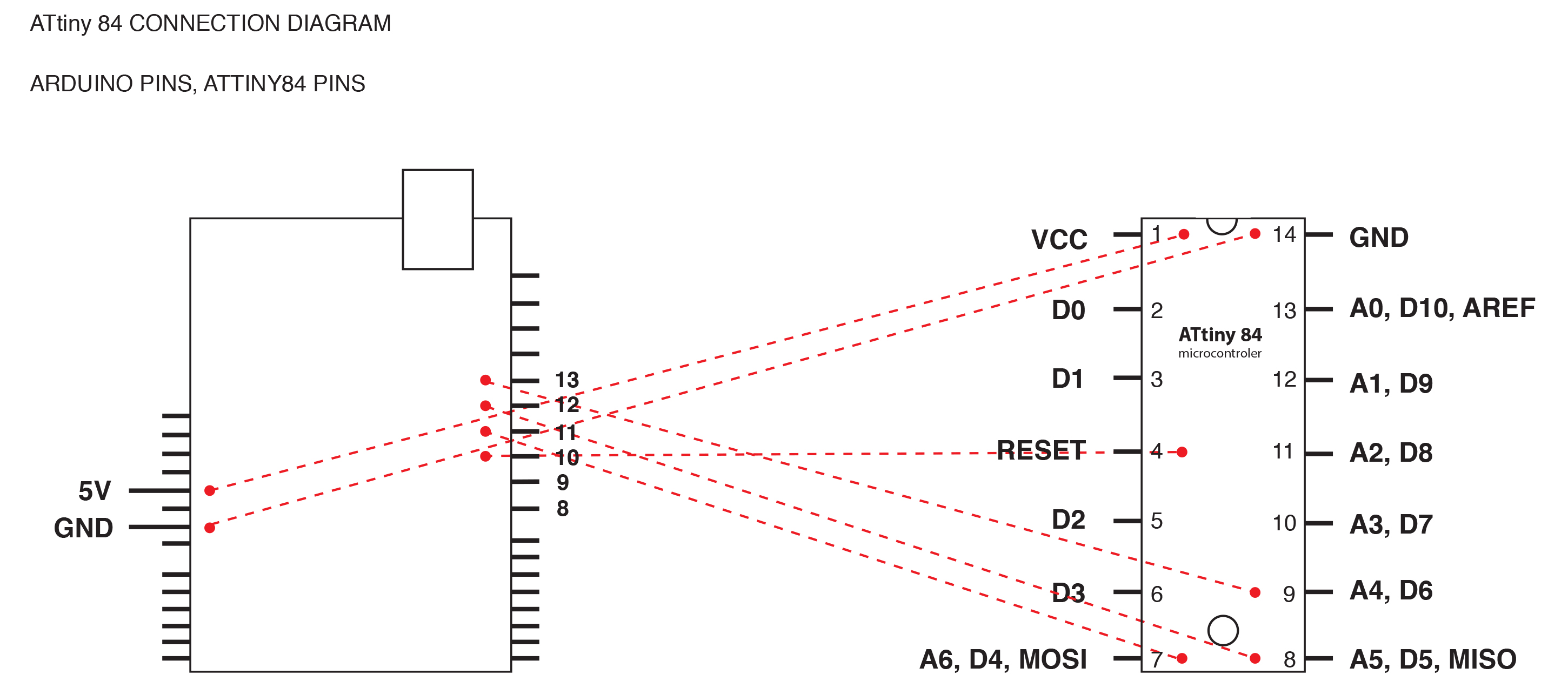
Arduino and ATtiny44/84 Connections
Arduino and ATtiny45/85 Connections
Step 5
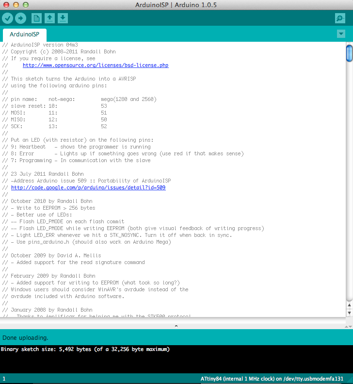
Before you start the wiring connections between the Arduino and the ATtiny84, you should first set the Arduino as an ISP programmer for the ATtiny. This operation allows the Arduino to program the ATtiny and pass the code to it. To set the Arduino as an ISP programmer you should launch the Arduino IDE and open the examples folder. Menu –> File –> Examples –> Arduino as ISP
Then assign the board that you are using. In our case it is the Arduino Uno board. To do that go to Menu –> Tools –> Board –> Arduino Uno
Make sure you have set the serial port correctly by going to Menu –> Tools –> Serial Port
Now your Arduino board operates as an ISP programmer.
Step 6
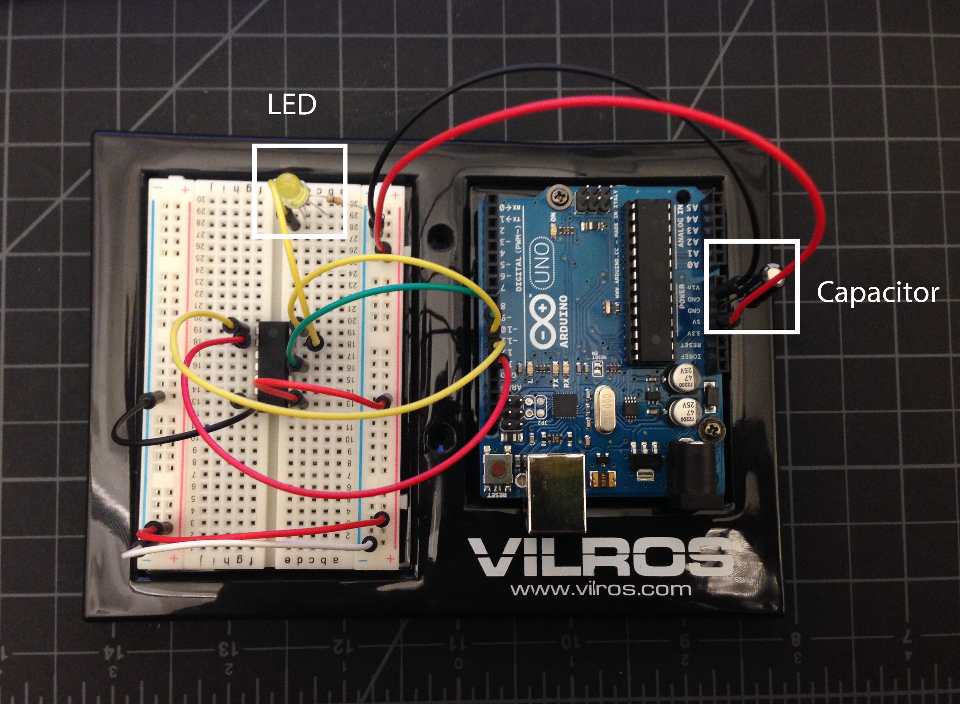
Complete the connections shown in the previous diagrams. In this tutorial we will go through the basic operation of blinking an LED light through the ATtiny board. For this simple operation you will require few more connections to be made. You will need an LED light, a resistor 330KΩ and a Capacitor 10uF. The capacitor is required in order to prevent the Arduino from resetting the bootloader, which we will go through later in this tutorial.
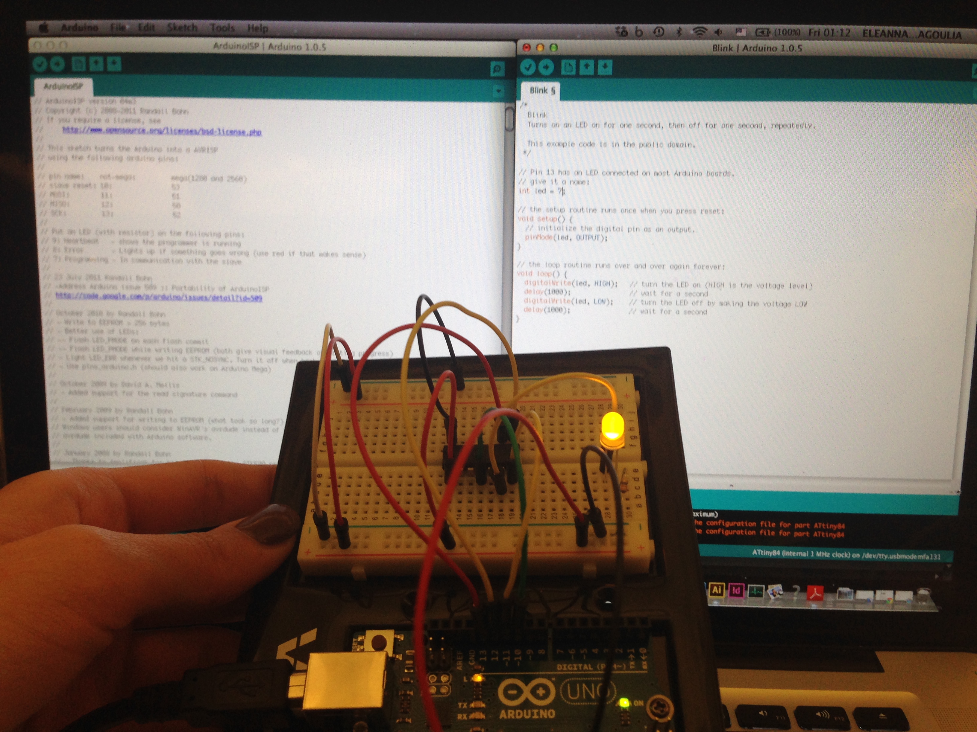
The following photo shows what the final connections should look like.
Step 7
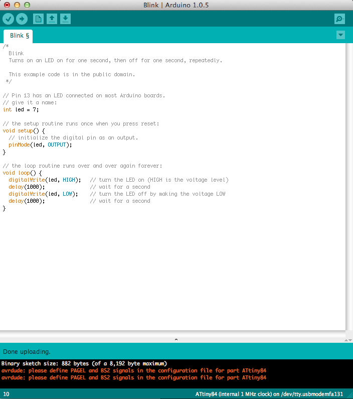
Open the Blink sketch from the example folder. Menu –> File –> Examples –> Basic –> Blink. In this sketch you will need to change the pin from 13 to 7.
Now you should have 2 Arduino sketches open in your screen
Step 8
Now you will set the ATtiny as your new board by going to Menu –> Tools –> Boards –> ATtiny84 1MHz. You can also operate on the ATtiny84 8MHz
Step 9
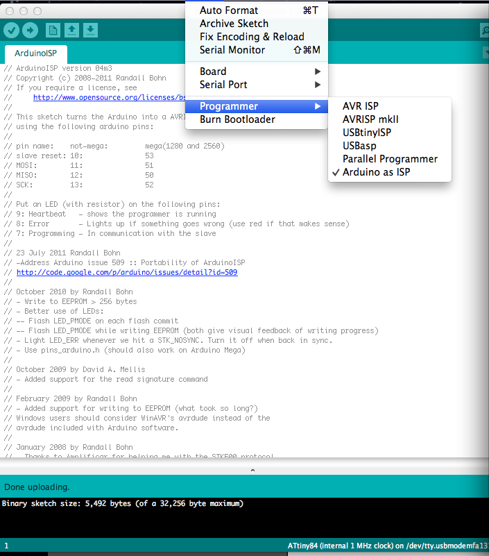
In this step you will assign the Arduino as ISP as the programmer of the ATtiny. Go to Menu –> Tools –> Programmer –> Arduino as ISP
Step 10
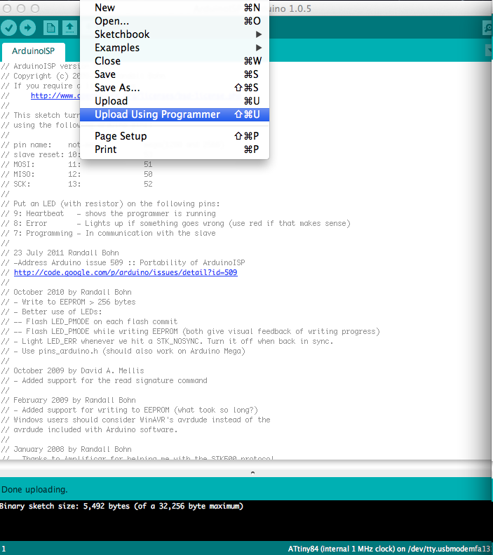
In order to upload the Blink sketch to the ATtiny you should go to Menu –> File –> Upload using Programmer
Step 10
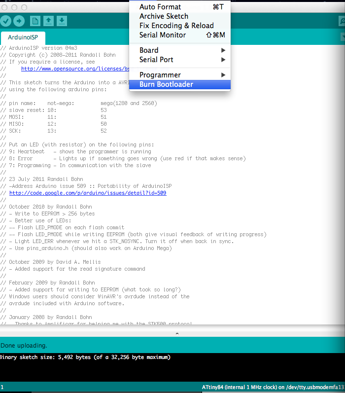
Burn Bootloader. This is not a mandatory step, however it is recommended. To burn the bootloader go to Menu –> Tools –> Burn Bootloader
Notice that the LED starts blinking. Now the blink sketch is stored in the ATtiny84.
Thank you!