Particle wave is a prototype installation that uses a string of LEDs, sensors, and Arduino microcontroller to reveal spatial and temporal changes in air pollution in the urban environment. The ultimate goal of the project is to create an array of poles that could be installed in vacant lots near freeways or other sources of urban air pollution.
Our first prototype works!
In the future we plan on using more accurate pollution sensors, refining the way that data is expressed through the RGB LEDs, and considering the deployment of similar device throughout the urban fabric instead of solely as a temporary art exhibit.
Wall adaptor power supply 9 volts (or other power source that can provide between 7 and 24 volts)
Hooking it up
The anemometer connects to the rest of the circuits through a single waterproof cable that bundles three wires. These three wires stick out of the end of the cable, each a different color: brown, black, and blue. The brown wire should be connected to the positive power source. The black should be connected to ground, and the blue is the output for the anemometer.
To more easily connect to the Arduino, wrap each wire from the anemometer around the male terminal of a jumper wire. Secure with an alligator clip (Figure 1).
Figure 1: Connecting the anemometer wires
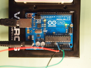
Using the jumper wire, connect the brown wire to the Vin pin (called 9V on some boards). Connect the black wire to one of the ground pins. Connect the blue output wire to one of the analog pins. For this tutorial we used pin A0. Figure 2 shows the circuit diagram for the entire assembly. Figure 3 shows the connections on an actual Arduino Uno.
Figure 2: Arduino attachments for anemometer
Figure 3: Arduino wiring
The anemometer requires a power source between 7V and 24V to produce a measurement. Arduinos use a lower voltage, between 3V and 5V, so the power coming to an Arduino through a USB connection isn’t enough to power the anemometer.
Instead, we’ll use another the external power supply on the board, sometimes labeled X1. This port accepts a female coaxial cable and is appropriate for ranges between 9V and 12V. To use this power source without damaging itself, the Arduino board uses a linear voltage reducer to bring it into the 3V-5V range. However, out anemometer can still access the full voltage if we connect it to the Vin pin (this is why this pin is labeled 9V on some boards).
You can use several sources for the external power supply. One option is to use a standard rectangular 9V battery. However, these batteries are designed for very low current uses for long periods of time (in smoke detectors, for example). The Arduino and anemometer will quickly use up the charge in the battery, leading to fluctuating voltages and bad readings from the sensor. The better option is to buy a wall adapter that produces 9V of steady, higher current power.
Once the wiring is complete and the external power source is connected, the hardware is ready to go. Lets get the software side up and running and measure some wind!
Software
The code for this tutorial takes the voltage output from the anemometer and uses the technical specs from Adafruit to convert the voltage into a wind speed. The anemometer is designed to output voltage between 0.4V and 2V. A value of 0.4V represents no wind and 2V represents a wind speed of 32.4 m/s. The relationship between voltage and wind speed is linear, meaning that each increase of 0.1V represents an increase of 2.025 m/s in wind speed. The following code maps the output values from the anemometer to wind speed using these values.
The Script
1
2
3
4
5
6
7
8
9
10
11
12
13
14
15
16
17
18
19
20
21
22
23
24
25
26
27
28
29
30
31
32
33
34
35
36
37
38
39
40
41
42
43
44
45
46
47
48
49
50
51
52
53
54
55
56
57
58
59
60
61
62
63
64
65
66
67
/*
Anemometer Tutorial
This code takes the output from an Adafruit anemometer (product ID 1733) and converts it into a wind speed.
The circuit:
Created 11 November 2014
By Joe Burg
Modified 11 November 2014
By Joe Burg
Hardware instructions and background information can be found at: http://www.hackerscapes.com/2014/11/anemometer/
Special thanks to Adafruit forum users shirad and adafruit_support_mike for help in trouble shooting code and hardward, including provided code of their own for comparison and inspiration.
*/
//Setup Variables
constintsensorPin=A0;//Defines the pin that the anemometer output is connected to
intsensorValue=0;//Variable stores the value direct from the analog pin
floatsensorVoltage=0;//Variable that stores the voltage (in Volts) from the anemometer being sent to the analog pin
floatwindSpeed=0;// Wind speed in meters per second (m/s)
floatvoltageConversionConstant=.004882814;//This constant maps the value provided from the analog read function, which ranges from 0 to 1023, to actual voltage, which ranges from 0V to 5V
intsensorDelay=1000;//Delay between sensor readings, measured in milliseconds (ms)
//Anemometer Technical Variables
//The following variables correspond to the anemometer sold by Adafruit, but could be modified to fit other anemometers.
floatvoltageMin=.4;// Mininum output voltage from anemometer in mV.
floatwindSpeedMin=0;// Wind speed in meters/sec corresponding to minimum voltage
floatvoltageMax=2.0;// Maximum output voltage from anemometer in mV.
floatwindSpeedMax=32;// Wind speed in meters/sec corresponding to maximum voltage
voidsetup()
{
Serial.begin(9600);//Start the serial connection
}
voidloop()
{
sensorValue=analogRead(sensorPin);//Get a value between 0 and 1023 from the analog pin connected to the anemometer
sensorVoltage=sensorValue *voltageConversionConstant;//Convert sensor value to actual voltage
//Convert voltage value to wind speed using range of max and min voltages and wind speed for the anemometer
if(sensorVoltage<=voltageMin){
windSpeed=0;//Check if voltage is below minimum value. If so, set wind speed to zero.
}else{
windSpeed=(sensorVoltage-voltageMin)*windSpeedMax/(voltageMax-voltageMin);//For voltages above minimum value, use the linear relationship to calculate wind speed.
}
//Print voltage and windspeed to serial
Serial.print("Voltage: ");
Serial.print(sensorVoltage);
Serial.print("\t");
Serial.print("Wind speed: ");
Serial.println(windSpeed);
delay(sensorDelay);
}
Thanks!
Thanks to the rest of the Particle Wave team for their review of the wiring and code for this tutorial. Special thanks to Adafruit forum users shirad and adafruit_support_mike for help in trouble shooting code and hardward, including provided code of their own for comparison and inspiration.