This tutorial shows how to light multiple LED’s one at a time through the use of either a force sensitive resistor or a potentiometer. Since both components deal with the increase or decrease of resistance through the circuit varying the voltage (which in our case is between 0 and 5v), both can be utilized with the same code.
First and foremost you’re going to need a few parts.
PARTS REQUIRED
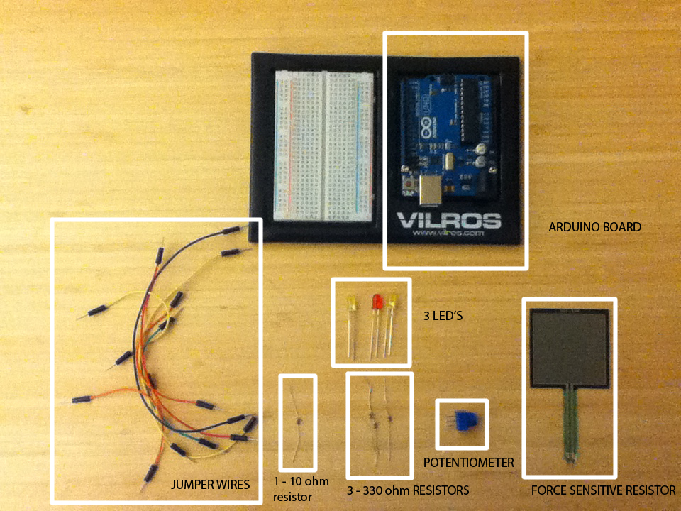
1. Arduino Kit
2. Force Sensitive Reisistor (FSR)
3. Potentiometer
4. 3 – 330 Ohm Resistors
5. 1 – 10 Ohm Resistor
6. Jumper Wires
7. 3 LED’s
8. Breadboard
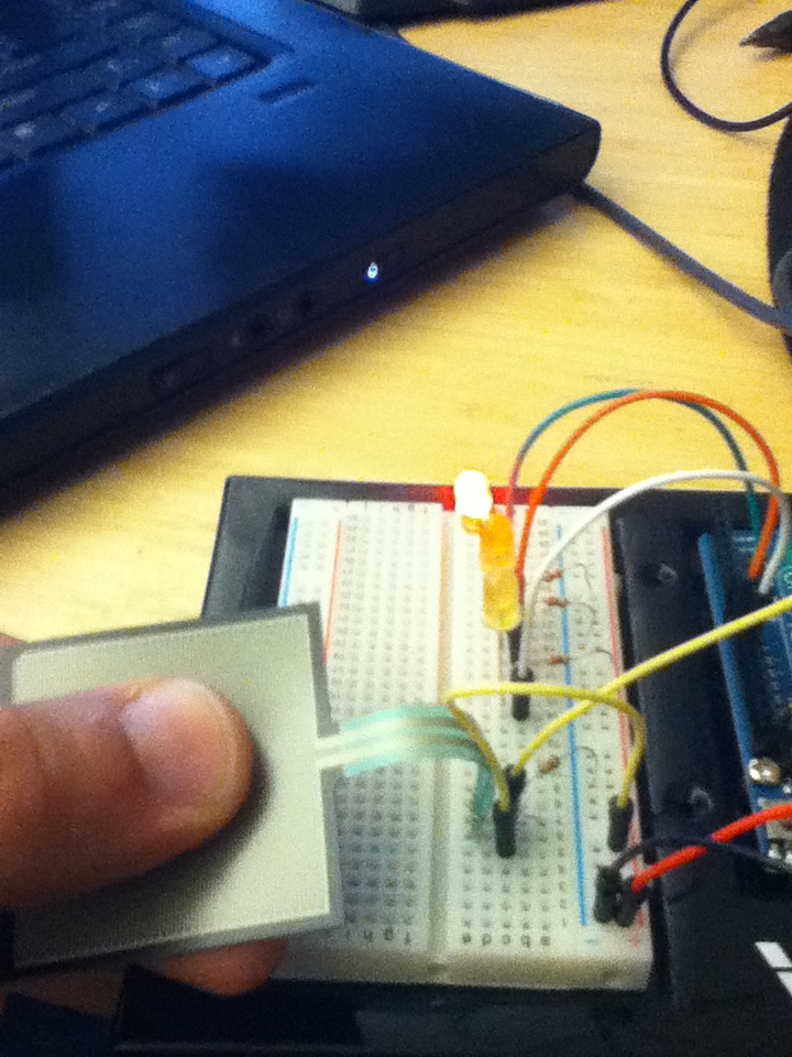
LIGHTING WITH FORCE SENSITIVE RESISTORS
Now that we have our parts, we’re going to start putting them together. Let’s start with the force sensitive resistor.
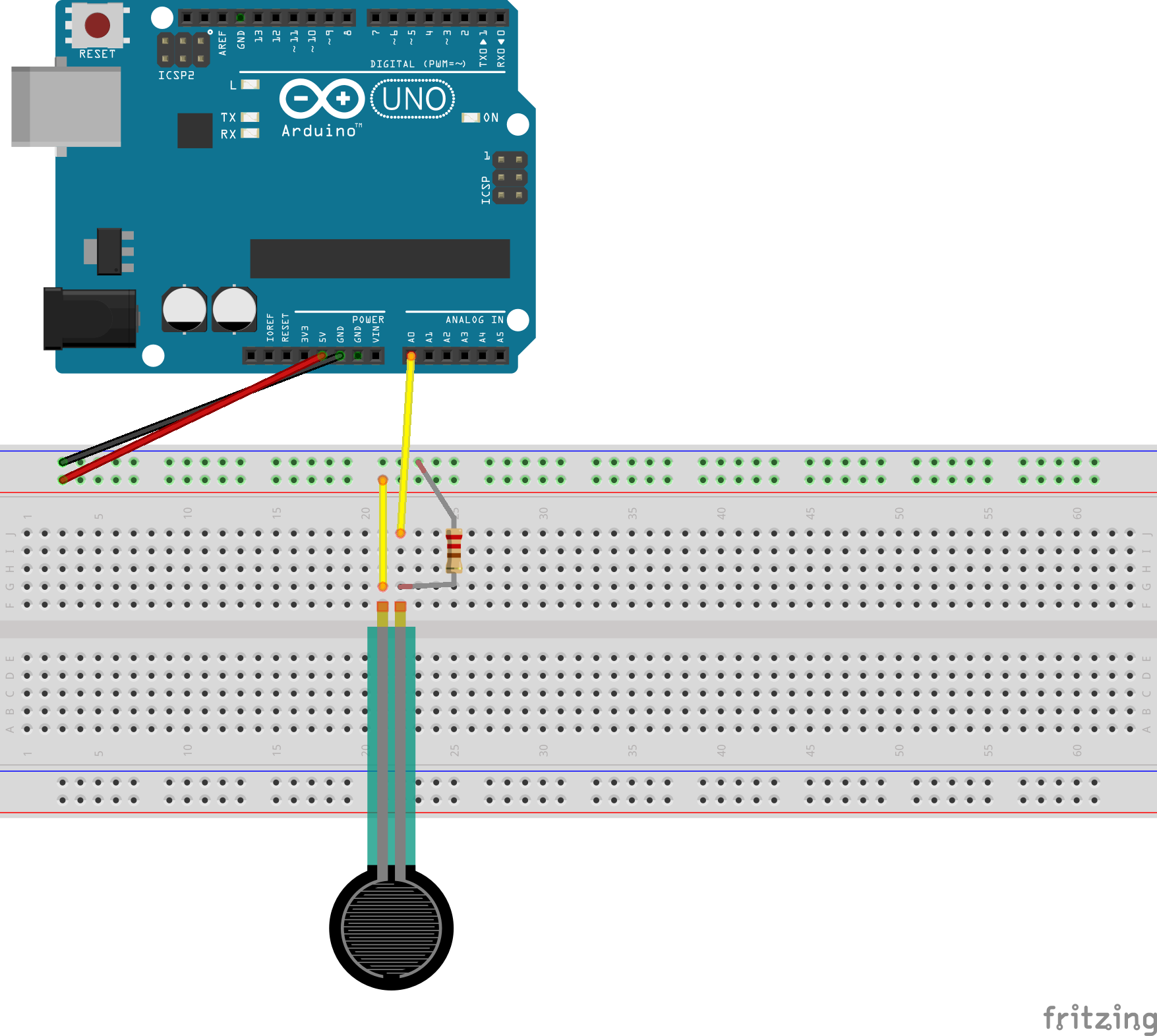
Connect your force sensitive resistor to the breadboard. From there, place a 10 Ohm resistor as shown in the diagram and connect that to ground by inserting one end of the resistor on the breadboard in the same column as the black wire. On the same row as the resistor insert a jumper wire and connect the other end of the jumper wire to the A0 pin on your arduino board. The ‘A0’ pin is your analogue pin that allows the sensor to communicate with your Arduino chip. Insert a second jumper wire from the sensor to the column of pins on the bread board that connects to the 5v power supply of your arduino kit (red wire).
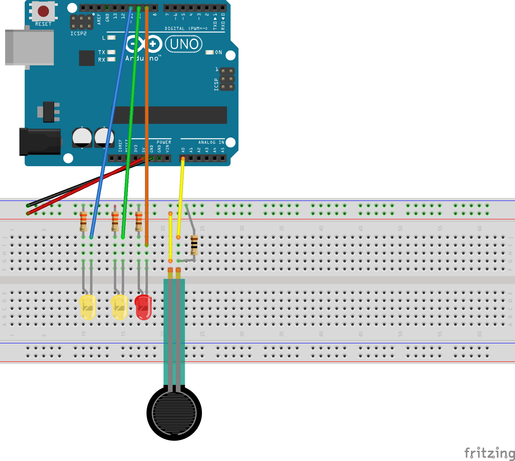
Now let’s start connecting our LED’s

Place an LED on the bread board. Once that is done place a 330 Ohm resistor from the negative end of the LED (shorter leg) to ground and a jumper wire from the positive end of the LED (longer leg) to digital pin 9. We’re using the digital pin because our LED’s are going to operate through information provided from the sensor to the arduino kit digitally.
Let’s do that for a number of LED;s.
So far so good! Now let’s put a code in there and try to light them up.
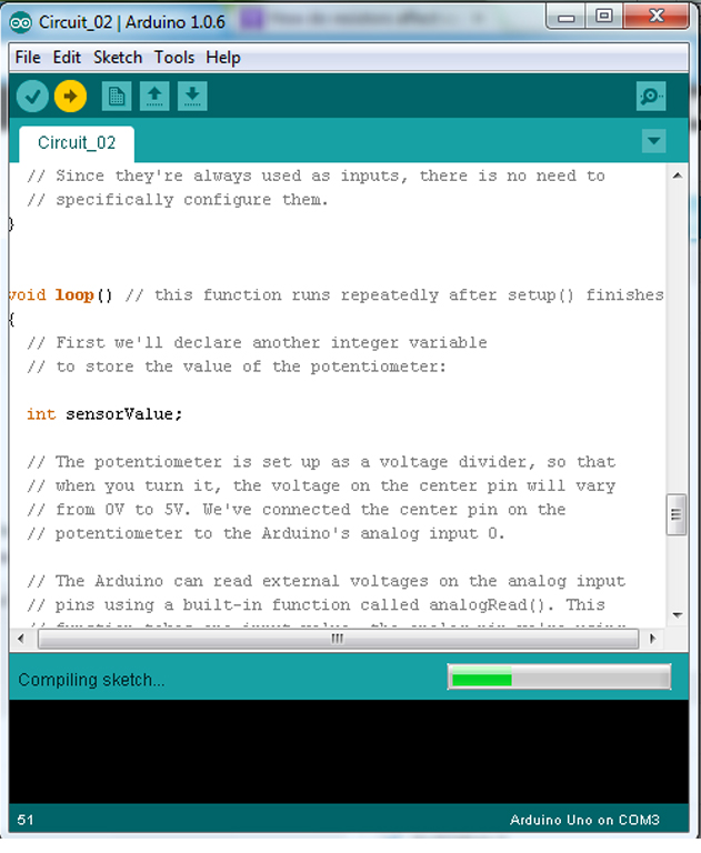
ARDUINO CODE
Let’s open up the arduino interface and start writing some code. Make sure your arduino is disconnected while coding so nothing burns out or short circuits.
|
1 2 3 4 5 6 7 8 9 10 11 12 13 14 15 16 17 18 19 20 21 22 23 24 25 26 27 28 29 30 31 32 33 34 35 36 37 38 39 40 41 42 43 44 |
//The following code was written with the reference of the online links mentioned below. //https://learn.adafruit.com/force-sensitive-resistor-fsr/using-an-fsr //http://www.instructables.com/id/Force-sensitive-resistor-activated-led/ // Lets "declare" variables so that the computer knows //about them when executing the code. We'll also need them so //we can refer to them later. //Variable names are case sensitive so type each name correctly //whenever you refer to it. int sensorPin = 0; // force sensitive resistor connected to analog pin 0 int ledPin1 = 9; //LED pin connected to digital pin 9 int ledPin2 = 10; //LED pin connected to digital pin 10 int ledPin3 = 11; //LED pin connected to digital pin 11 int sensorValue = 0; void setup() // This funtion runs once the sketch starts up. // We'll be using pin 9, 10 and 11 to light the LED so it's important //to refer to it as an output. We've named it ledPin. { Serial.begin(9600); // starting up your serial monitor to view varying values pinMode(ledPin1, OUTPUT); pinMode(ledPin2, OUTPUT); pinMode(ledPin3, OUTPUT); } void loop() // This funtion runs repeatedly after setup()is completed { sensorValue = analogRead(sensorPin); //reading the values from the analog pin of the sensor // and throwing it out as a value Serial.print("Force value = "); //Display value "Force value" Serial.println(sensorValue); if(sensorValue > 0 && sensorValue <= 500) // an "if" statement giving a condition //for the values that will allow you to switch between LED's. { digitalWrite(ledPin1, HIGH); // this is to say if the above statement is // the LED shoud light up } else digitalWrite(ledPin1, LOW); // this is to say that if the above statement //is not true the LED should turn or remain off. if(sensorValue > 500 && sensorValue <= 800) { digitalWrite(ledPin2, HIGH); } else digitalWrite(ledPin2, LOW); if(sensorValue > 800) { digitalWrite(ledPin3, HIGH); } else digitalWrite(ledPin3, LOW); } |
Once you’ve written the code connect your arduino port to the computer and click on the ‘upload’ icon (which is shaped like an arrow) at the top left corner of your interface (right below the edit menu).
If you run the code before connecting the arduino to your computer you might run into a serial port error.

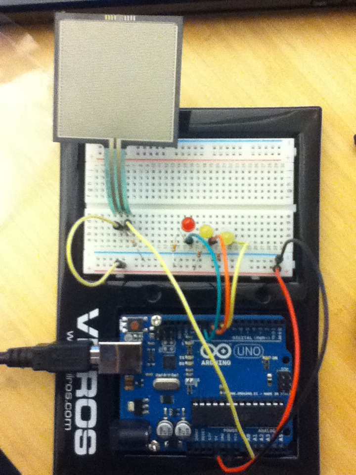
If you have gotten everything running smoothly, press on the force sensitive resistor with different pressures and watch the LED’s change.
LIGHTING WITH A POTENTIOMETER
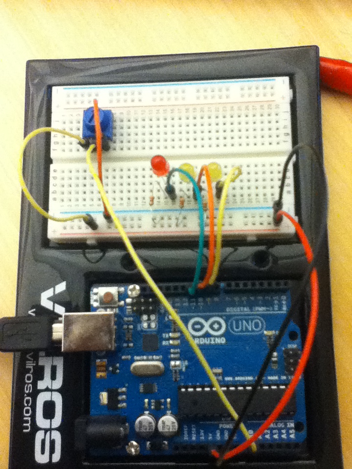
Now let’s see how we can light up the LED’s using a potentiometer. The thing to note here is that since the code works the same we can repeat all the steps above but replace the force sensitive resistor with the potentiometer.
The circuitry:
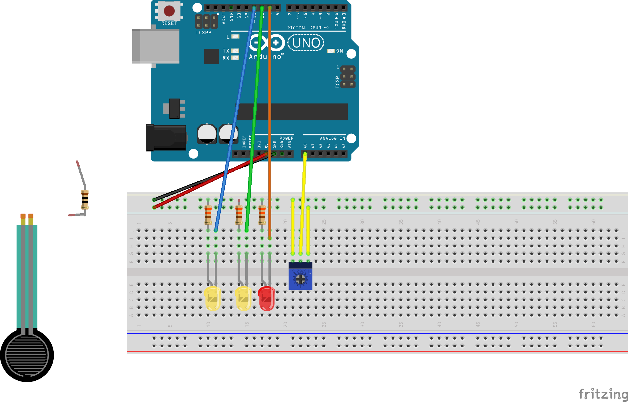
Insert the potentiometer on to the breadboard and connect jumper wires from the breadboard to the arduino board as shown in the diagram above. The middle jumper wire should be connected to the analog 0 pin as this is going to help determine the varying resistance values that will switch between LED’s. Once the potentiometer is plugged in and you have run the code through arduino, rotate the dial on the potentiometer and watch the LED’s change.
You can potentially develop some very interesting projects with the use of LED’s and sensors especially in an urban context when there is a lot of activity and the circuit is constantly being activated.