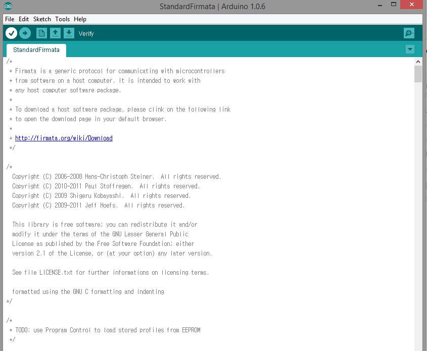
This tutorial describes the process of direct communication between Arduino and Processing. I wish to learn this process, in order to overcome possible serial port problems between Arduino and Processing during serial communication. Moreover, direct control of Arduino board through Processing, results in a more clear and straight forward process. When considering the Arduino library in Processing allow us to get the data from the board automatically with no concerning about pins and its certain data array. This process is enabled by a special library called “StandardFirmata”, that allows data to be transferred automatically from Arduino to Processing by simplifying significantly the initialization of pins and data arrays. First of all, upload the library called “StandardFirmata”, which is located in the examples file of the Arduino sketch window. 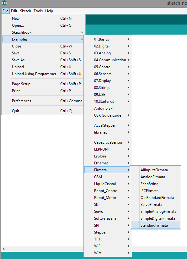
 Since the library is uploaded correctly, the further steps of the process do not involve the Arduino window. The next step would be to create an example sketch in Processing in order to demonstrate the process. Open a Processing sketch and follow the code with the embedded comments below. Tutorial: Step A: Blink an LED with digitalWrite function
|
1 2 3 4 5 6 7 8 9 10 11 12 13 14 15 16 17 18 19 20 21 22 23 24 25 26 27 28 29 30 31 32 33 34 35 36 37 38 39 40 41 42 43 44 45 46 47 48 49 50 51 52 53 54 55 56 57 |
///////////////////////////////////////////////////////// // Hackerscapes Fall 2014 LD Arch 254 // Communication between Arduino board and Processing directly // Arduino Uno and Processing 2.2.1 // // NJ Namju Lee, // 2014.11 ///////////////////////////////////////////////////////// // Tutorial Step A , blink LED with digitalWrite fuction ///////////////////////////////////////////////////////// // USAGE // clikc the processing sketch to blink a LED ///////////////////////////////////////////////////////// // import libraries to use functions for serial and arduino communication import processing.serial.*; import cc.arduino.*; // declare a variable for Arduino library Arduino arduino; // setup like the setup in Arduino programming void setup() { // define the size of sktech where we can do interaction processing with Arduino size(470, 200); frameRate(10); //print a list of the available serial devices. If your Arduino board is connected //to the computer when you call this function, its device will be in the list. println(Arduino.list()); // assign Arduino class based on the serial into the variable that we made arduino = new Arduino(this, Arduino.list()[0], 57600); } // draw is the same as the loop in Arduino programming void draw() { background(0,0,0); } // As a function in Arduino programming, // we can built our own functions including diverse mouse events in processing. // executing the fuction below when mouse is pressed void mousePressed() { // call the fuction about digitalWrite for the pin 10 in order to turn on the LED arduino.digitalWrite(7, Arduino.HIGH); background(255); } // executing the fuction below when mouse is released void mouseReleased() { // call the fuction about digitalWrite for the pin 10 in order to turn off the LED arduino.digitalWrite(7, Arduino.LOW); } |
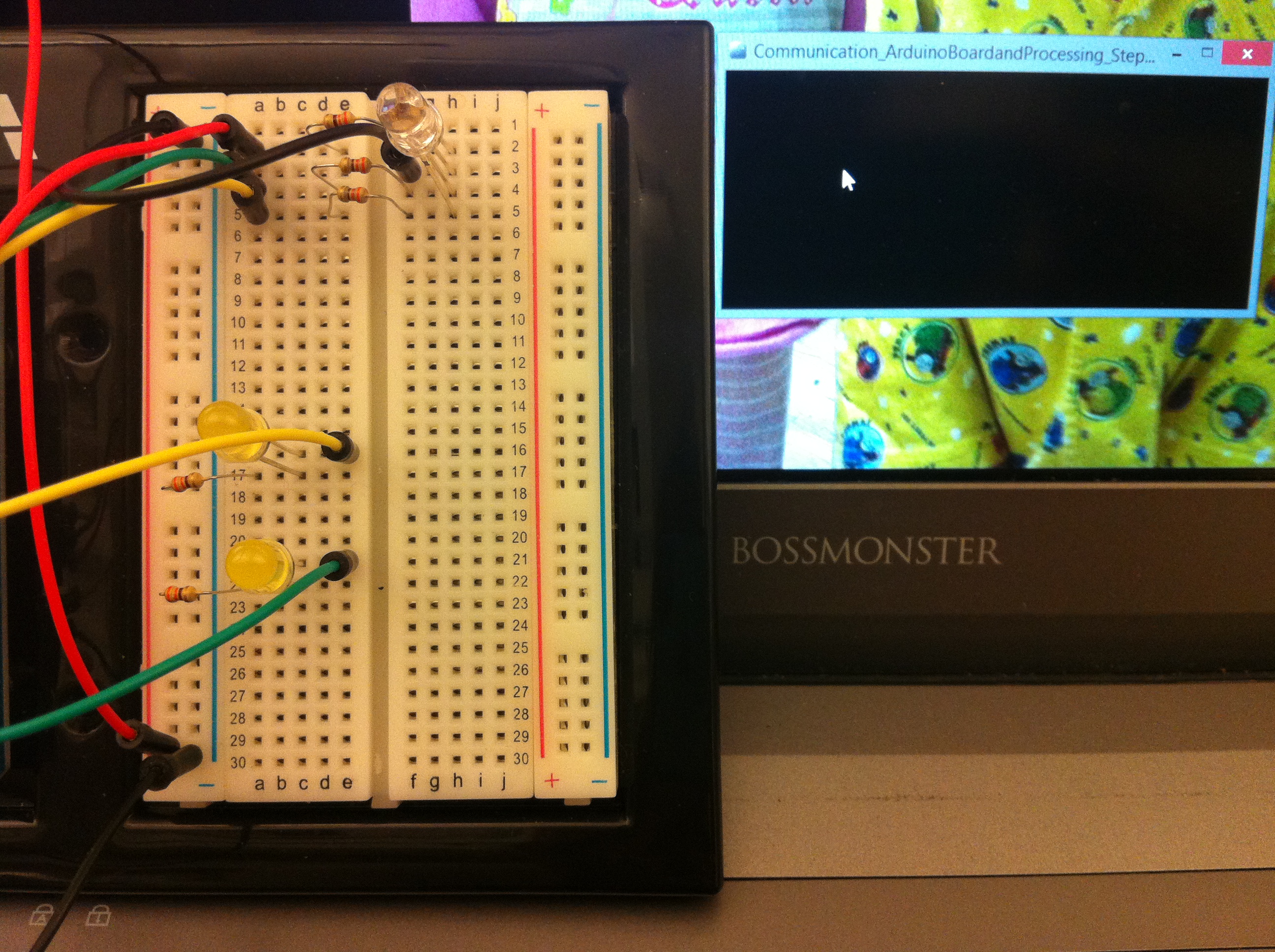 Click on the Processing sketch to blink an LED Click on the Processing sketch to blink an LED
 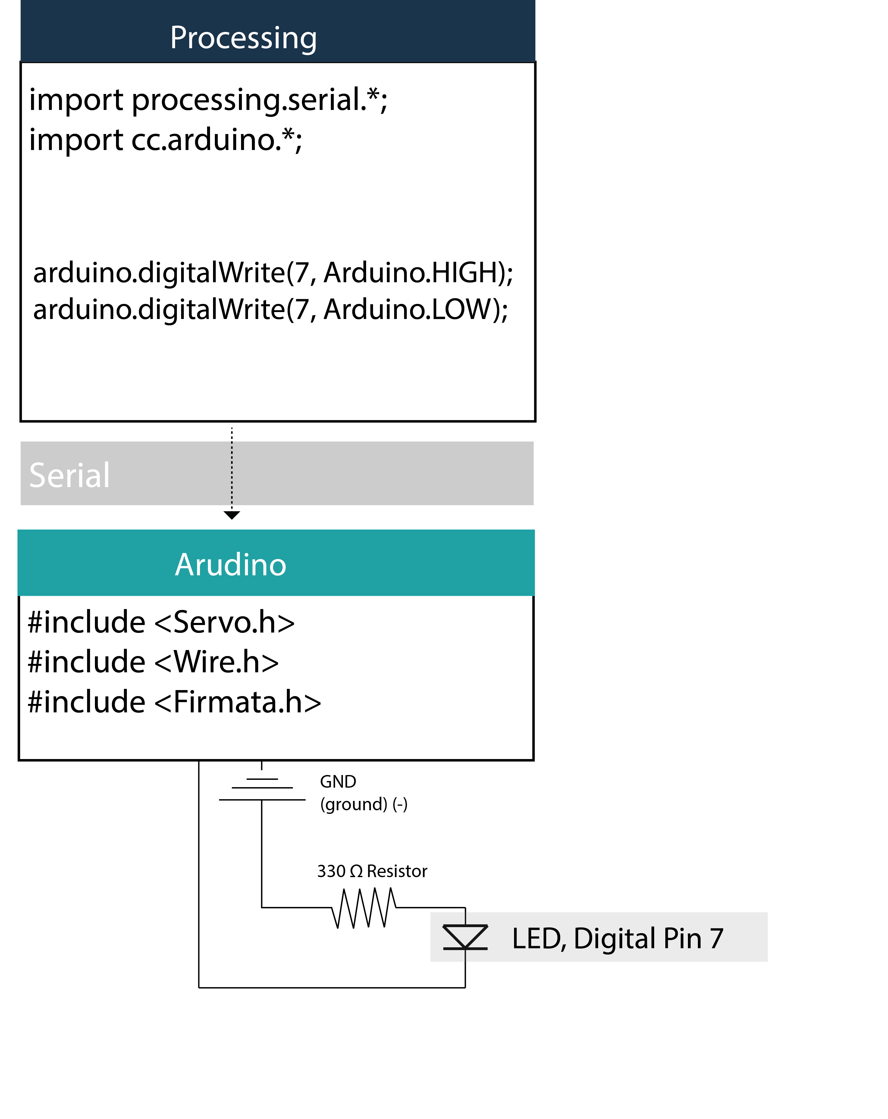 Tutorial: Step B: Changing LED brightness with analogWrite function based on mouse position
|
1 2 3 4 5 6 7 8 9 10 11 12 13 14 15 16 17 18 19 20 21 22 23 24 25 26 27 28 29 30 31 32 33 34 35 36 37 38 39 40 41 42 43 44 45 46 47 48 49 50 51 52 53 54 55 56 57 58 59 60 61 |
///////////////////////////////////////////////////////// // Hackerscapes Fall 2014 LD Arch 254 // Communication between Arduino board and Processing directly // Arduino Uno and Processing 2.2.1 // // NJ Namju Lee, // 2014.11 ///////////////////////////////////////////////////////// // Tutorial Step B , Changing LED brightness with analogWrite fuction based on mouse position ///////////////////////////////////////////////////////// // USAGE // moving mouse on the processing sketch to change LED brightness ///////////////////////////////////////////////////////// // import libraries to use functions for serial and arduino communication import processing.serial.*; import cc.arduino.*; // declare a variable for Arduino library Arduino arduino; int value; int count = 1; // setup like the setup in Arduino programming void setup() { // define the size of sktech where we can do interaction processing with Arduino size(255*2, 200); frameRate(60); //print a list of the available serial devices. If your Arduino board is connected //to the computer when you call this function, its device will be in the list. println(Arduino.list()); // assign Arduino class based on the serial into the variable that we made arduino = new Arduino(this, Arduino.list()[0], 57600); gradientBG(); } // draw is the same as the loop in Arduino programming void draw() { // 60 frame in a second, based on the mouse's X position, the LED light's brightness can be interacted arduino.analogWrite(6, value); //arduino.digitalWrite(7, Arduino.HIGH); } void mouseMoved() { // when mouse is moved, the value is redefined by mouse's X position. // the reason divide the value by 2 is that the sketch is double size of 255 which is maximum value of LED, // in order to match the size of processing's sketch with the light range of LED. value = mouseX/2; } // This function draw gradient background from black to white color in the sketch of processing // The background color indicate the Arduino LED intensity as a gradient color value void gradientBG(){ for (int i = 0; i < width; i += 2){ strokeWeight(2); stroke(i/2); line(i,0, i,height); } } |
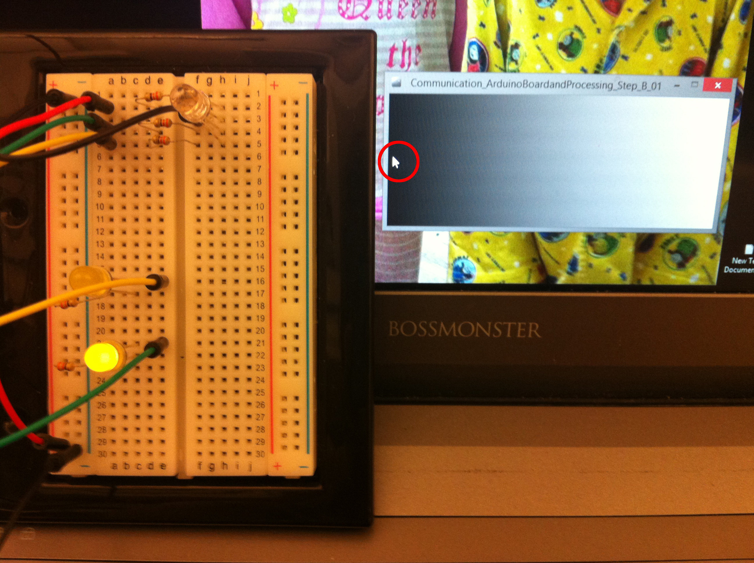 Changing LED brightness with analogWrite fuction based on mouse position, the left of the sketch of Processing, value = 10
 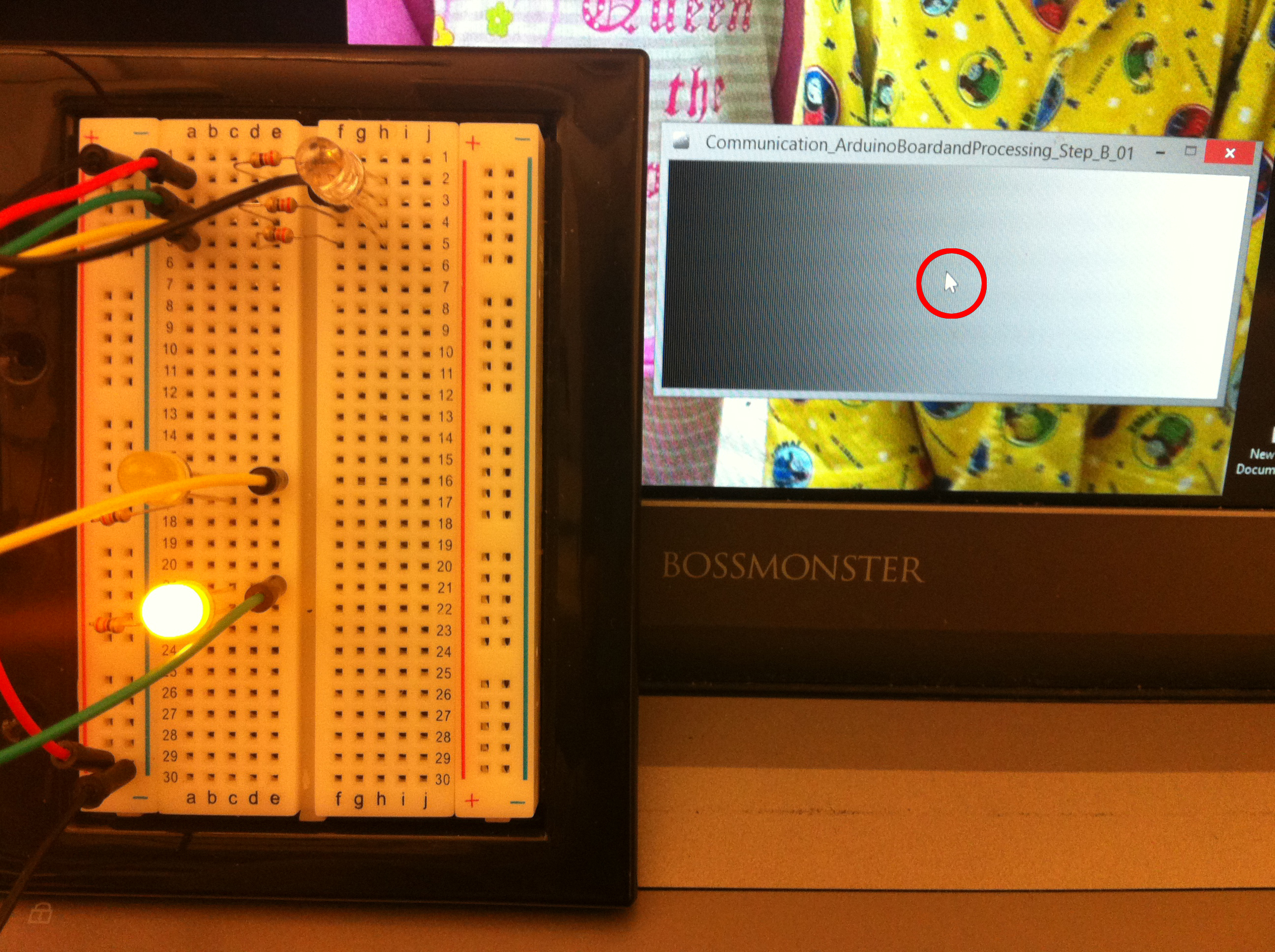 Changing LED brightness with analogWrite function based on mouse position, Processing window middle position, value = 180
 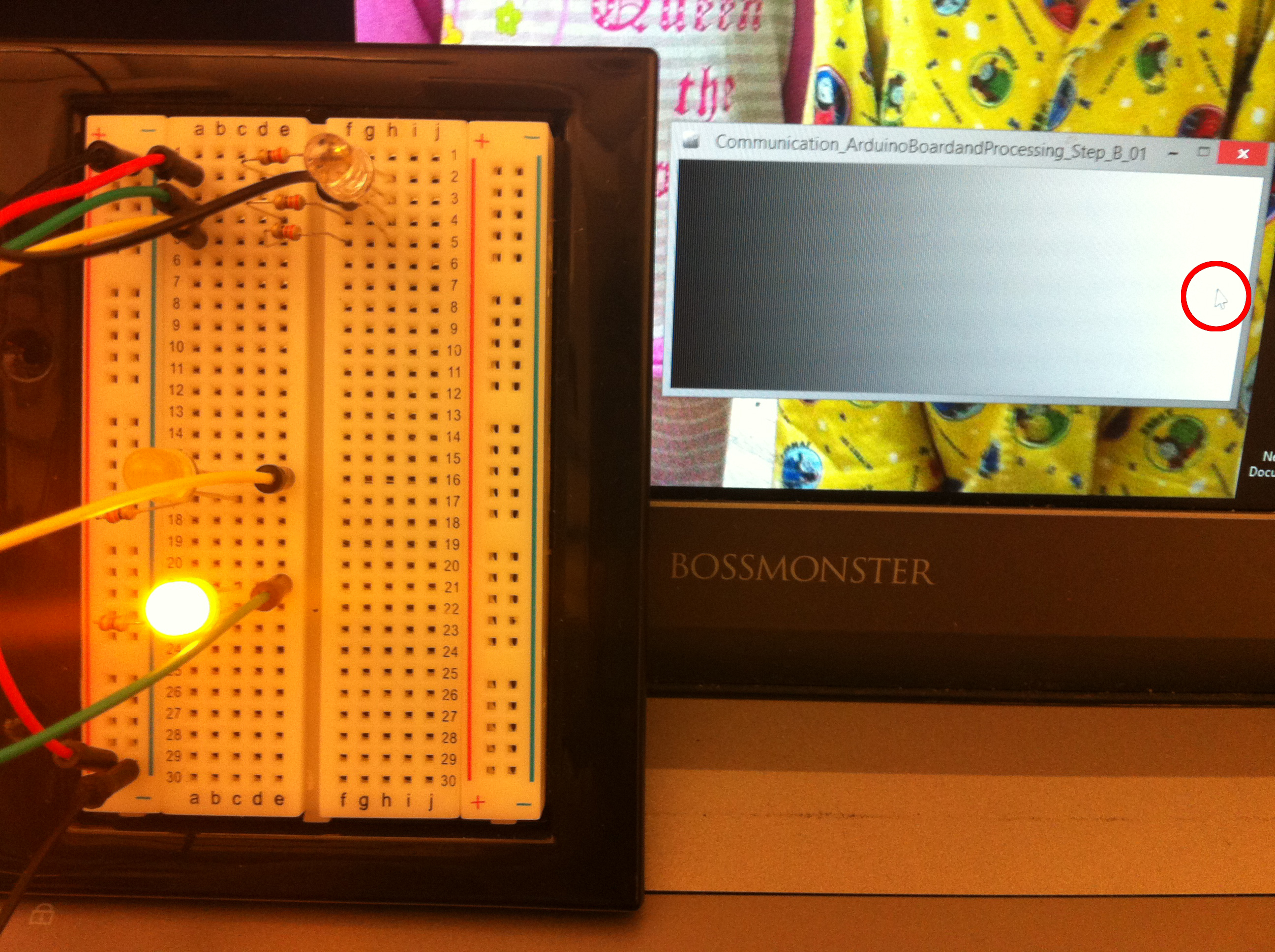 Changing LED brightness with analogWrite function based on mouse position, Prossesing window right side, value = 255
  Tutorial: Step C: Changing RGB LED brightness with analogWrite function based on mouse position
|
1 2 3 4 5 6 7 8 9 10 11 12 13 14 15 16 17 18 19 20 21 22 23 24 25 26 27 28 29 30 31 32 33 34 35 36 37 38 39 40 41 42 43 44 45 46 47 48 49 50 51 52 53 54 55 56 57 58 59 60 61 62 63 64 65 66 67 68 69 70 71 72 |
///////////////////////////////////////////////////////// // Hackerscapes Fall 2014 LD Arch 254 // Communication between Arduino board and Processing directly // Arduino Uno and Processing 2.2.1 // // NJ Namju Lee, // 2014.11 ///////////////////////////////////////////////////////// // Tutorial Step C , Changing RGB LED brightness with analogWrite fuction based on mouse position ///////////////////////////////////////////////////////// // USAGE // Click and drag the handles of red, green, and blue in order to change RGB LED brightness and combination /////////////////////////////////////////////////////////////// // reference, Handles example in Processing // import libraries to use functions for serial and arduino communication import processing.serial.*; import cc.arduino.*; // declare a variable for Arduino library, and an array for Handele class Arduino arduino; Handle[] handles; // declare a variable for red, green, blue in order to send them to Arduino board int r; int g; int b; void setup() { size(520, 130); //print a list of the available serial devices. If your Arduino board is connected //to the computer when you call this function, its device will be in the list. println(Arduino.list()); // assign Arduino class based on the serial into the variable that we made arduino = new Arduino(this, Arduino.list()[0], 57600); // assign handle class into three handles in array int num = height/3; handles = new Handle[num]; int hsize = 10; for (int i = 0; i < 3; i++) { handles[i] = new Handle(width/12, 10+i*50, 50-hsize/9, 10, handles); } } void draw() { background(255); // Based on mouse event, the handles class changes its handles sketch to show animation // and the class return its value, and save the value of r, g , b r = handles[0].update(); handles[0].display(); g = handles[1].update(); handles[1].display(); b = handles[2].update(); handles[2].display(); //The r,g,b value apply the analogWrite function as an intensity level arduino.analogWrite(9, r); arduino.analogWrite(10, g); arduino.analogWrite(11, b); } // As a mouse event, when mouse is released, it executes the releaseEvent in the class. void mouseReleased() { for (int i = 0; i < 3; i++) { handles[i].releaseEvent(); } } |

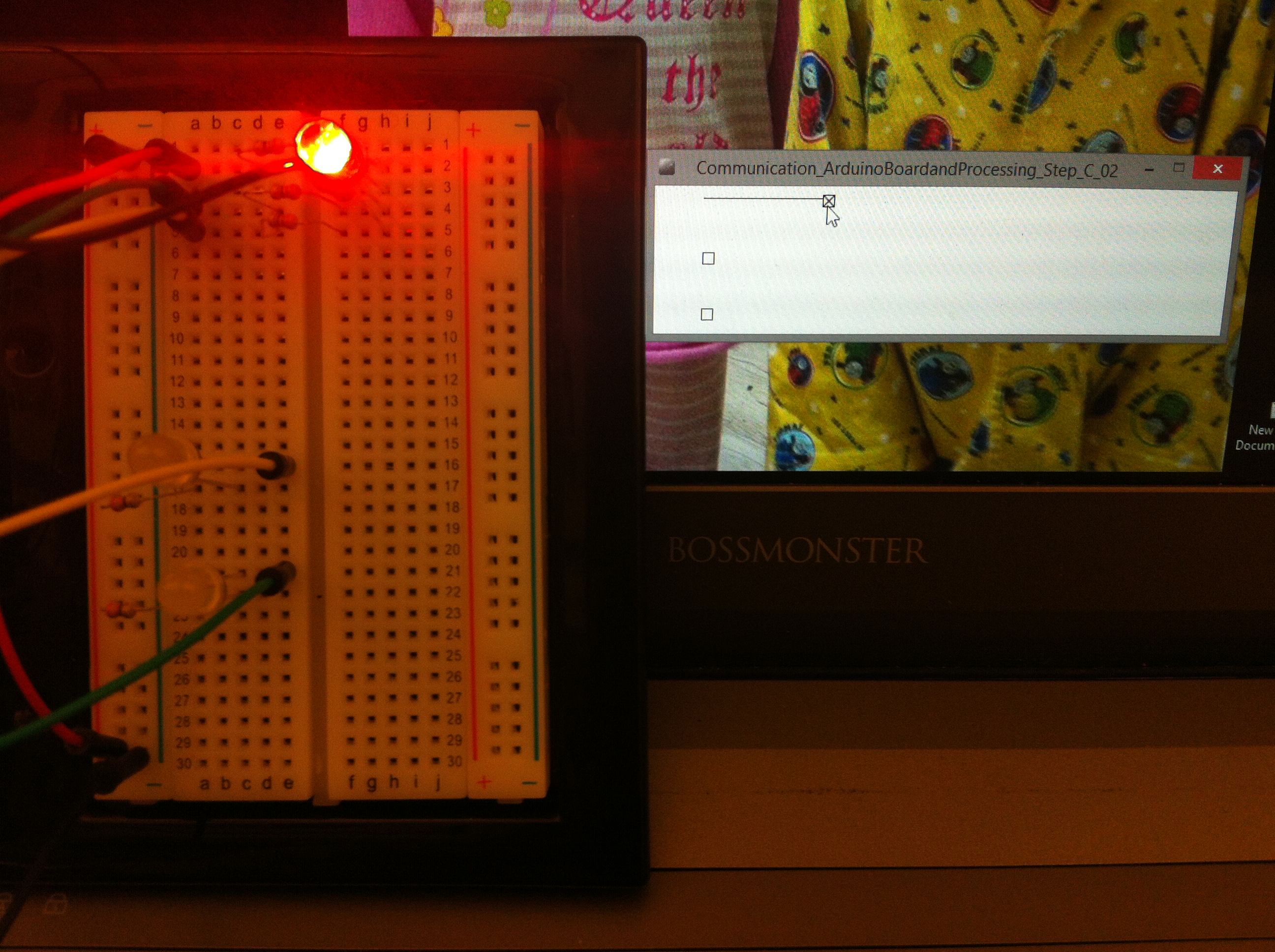 Changing RGB LED brightness with analogWrite function based on handle, value = red
 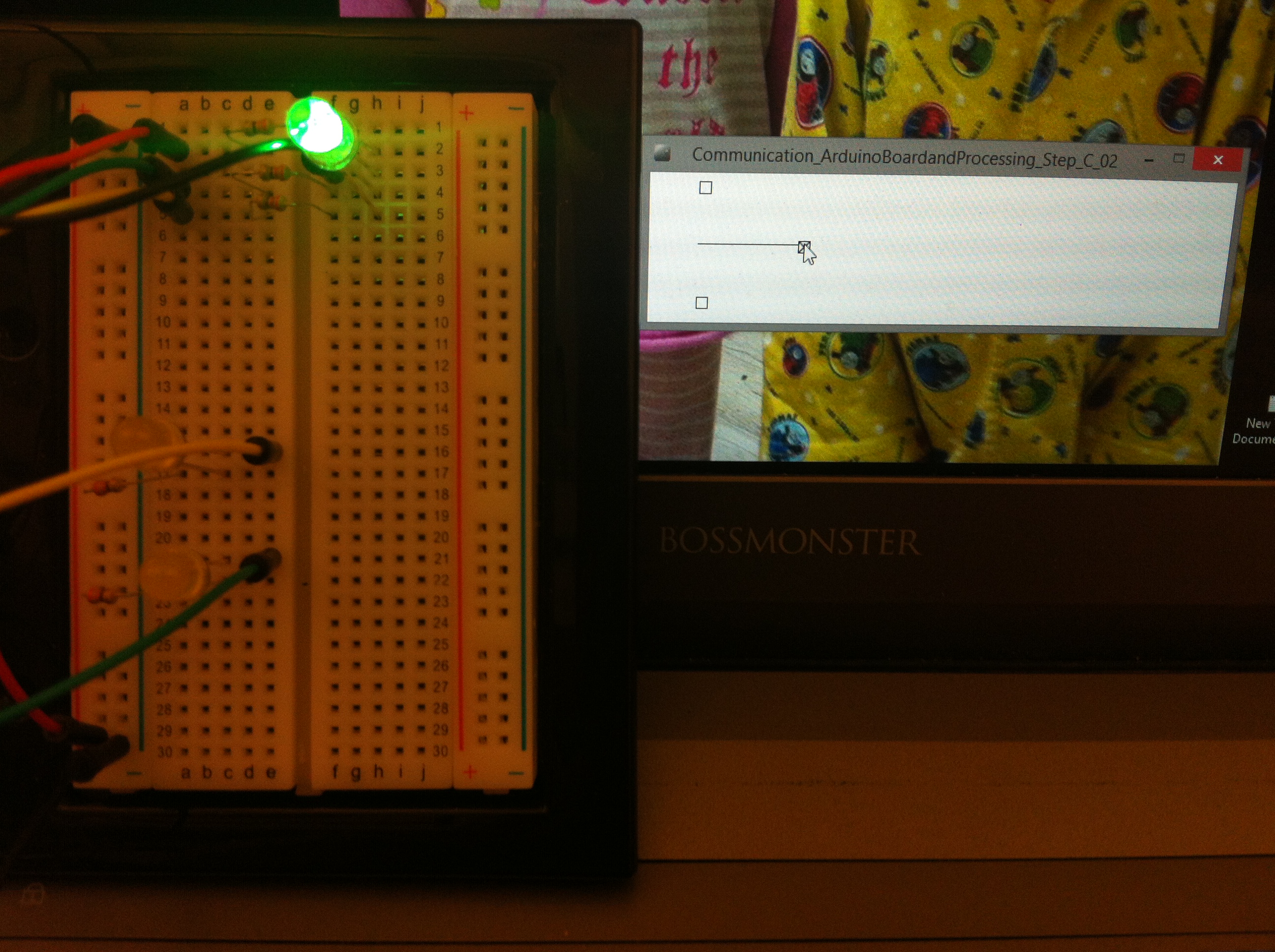 Changing RGB LED brightness with analogWrite function based on handle, value = green
 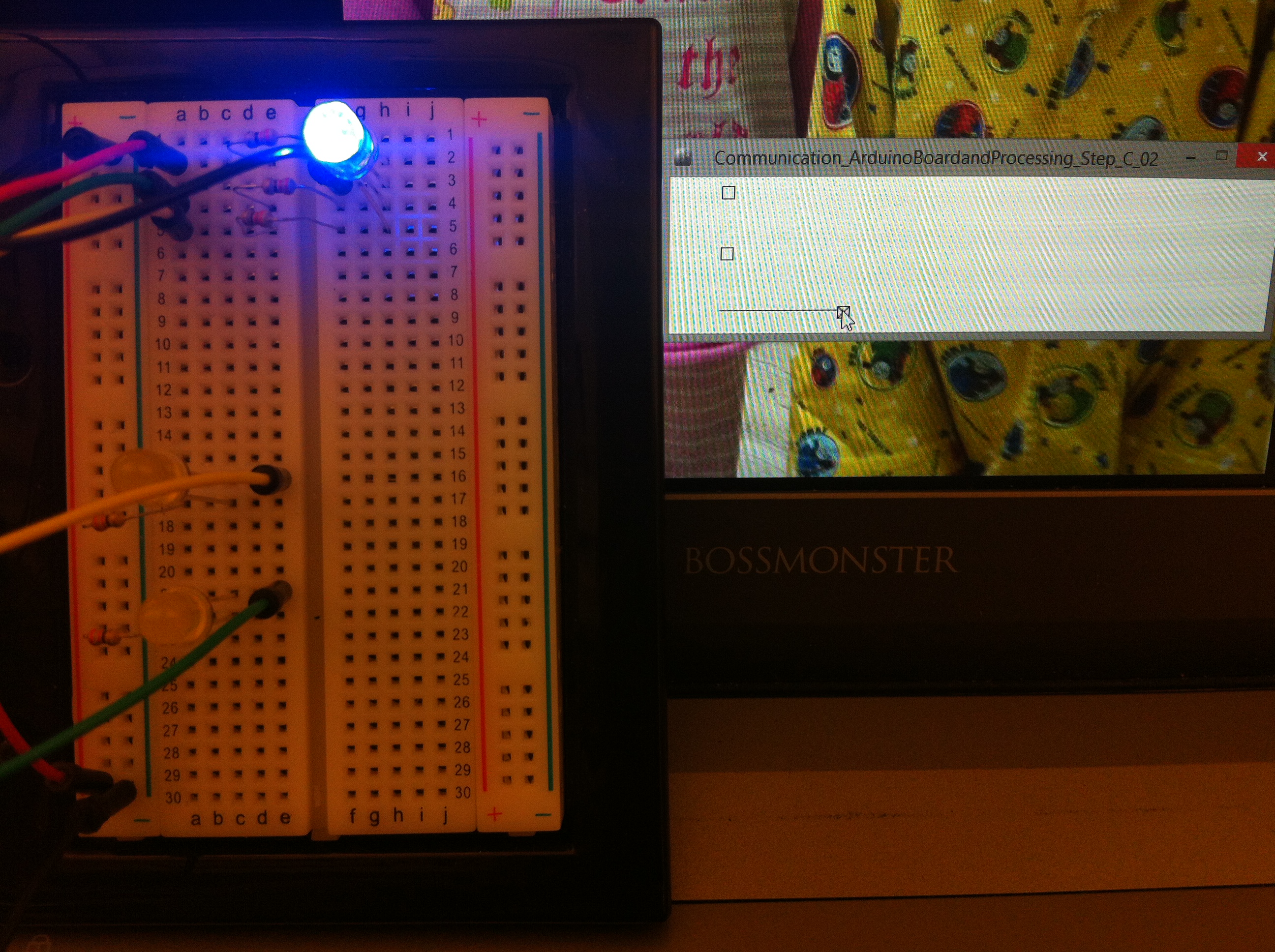 Changing RGB LED brightness with analogWrite function based on handle, value = blue
 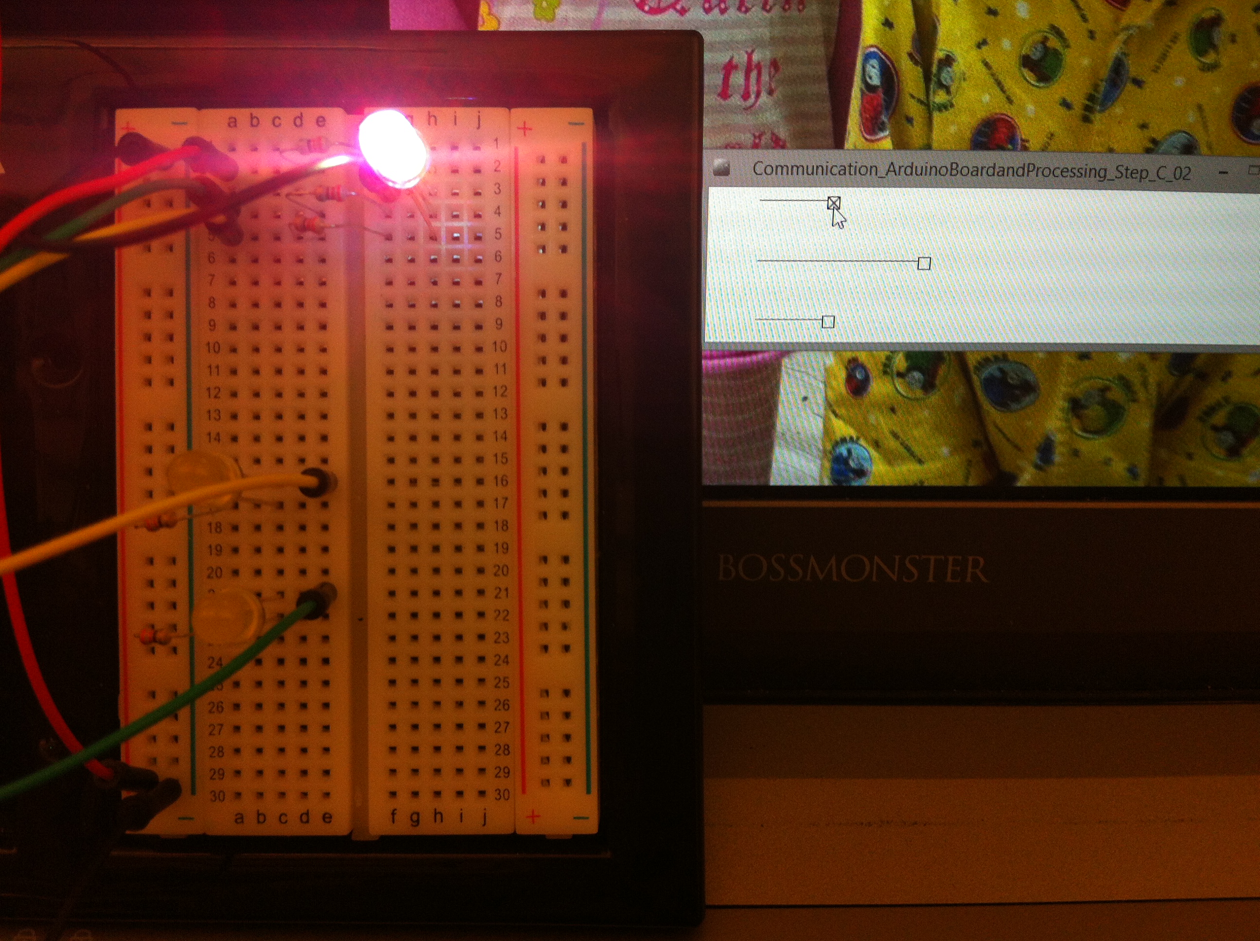 Changing RGB LED brightness with analogWrite fuction based on handle, value R G B combination
 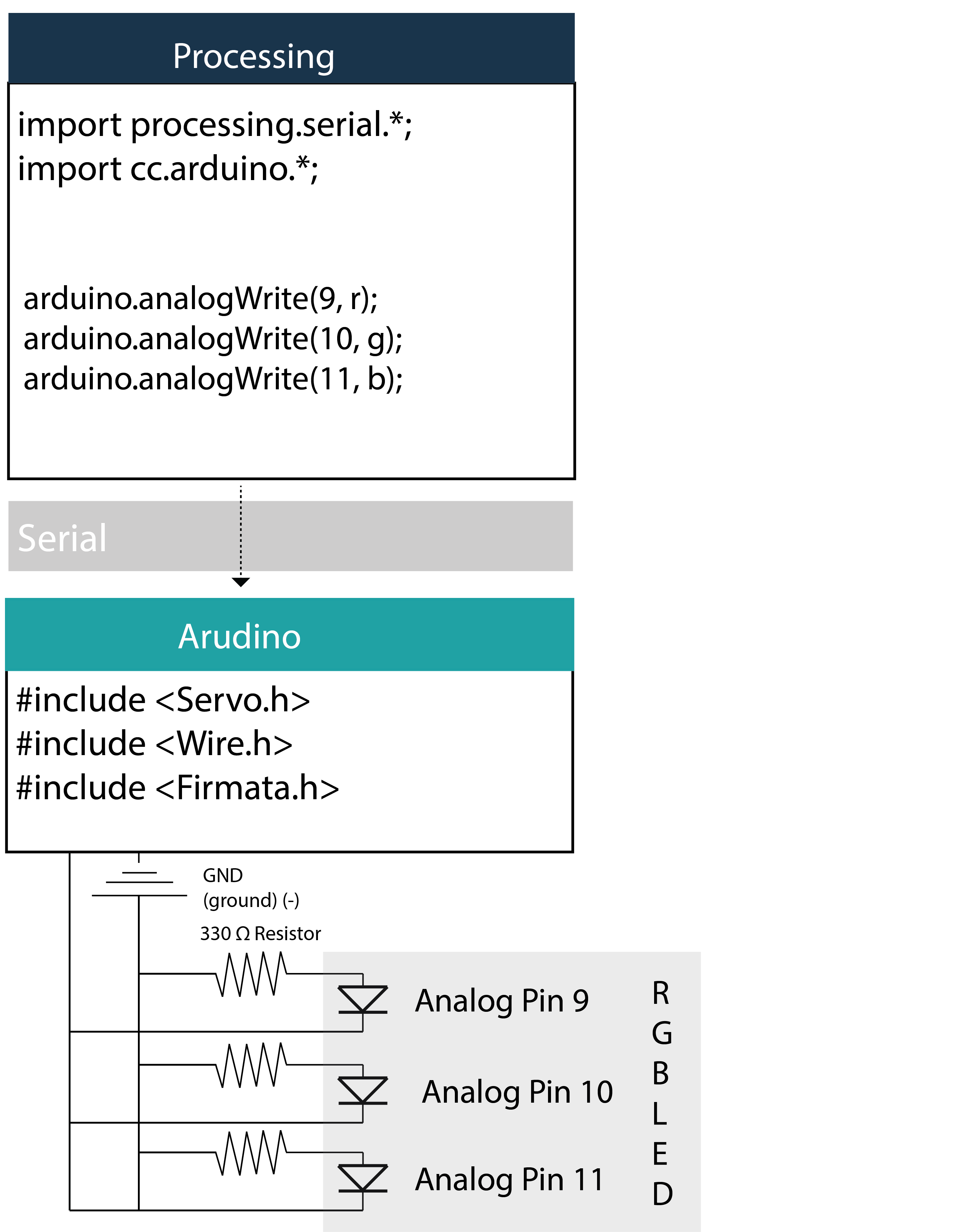 Tutorial: Step D: Analogue Read (Photo Resistor) from Arduino and data visualization in Processing
|
1 2 3 4 5 6 7 8 9 10 11 12 13 14 15 16 17 18 19 20 21 22 23 24 25 26 27 28 29 30 31 32 33 34 35 36 37 38 39 40 41 42 43 44 |
///////////////////////////////////////////////////////// // Hackerscapes Fall 2014 LD Arch 254 // Communication between Arduino board and Processing directly // Arduino Uno and Processing 2.2.1 // // NJ Namju Lee, // 2014.11 ///////////////////////////////////////////////////////// // Tutorial Step D , Read analogue data from Arduino, visualize the data in processing ///////////////////////////////////////////////////////// // import libraries to use functions for serial and arduino communication import processing.serial.*; import cc.arduino.*; // declare a variable for Arduino library Arduino arduino; int photo_resistor; // setup like the setup in Arduino programming void setup() { // define the size of sktech where we can do interaction processing with Arduino size(470, 200); frameRate(10); //print a list of the available serial devices. If your Arduino board is connected //to the computer when you call this function, its device will be in the list. println(Arduino.list()); // assign Arduino class based on the serial into the variable that we made arduino = new Arduino(this, Arduino.list()[0], 57600); } // draw is the same as the loop in Arduino programming void draw() { // refresh the background color as the value from the Photo Resistor in Aurdino board. background(photo_resistor); // read the the analog pin of the number "0" from the board photo_resistor = arduino.analogRead(0); // remap the analogue data because the background color in processing need the integer data from 0 to 255 photo_resistor = int(map(photo_resistor, 180, 580, 0, 255)); } |
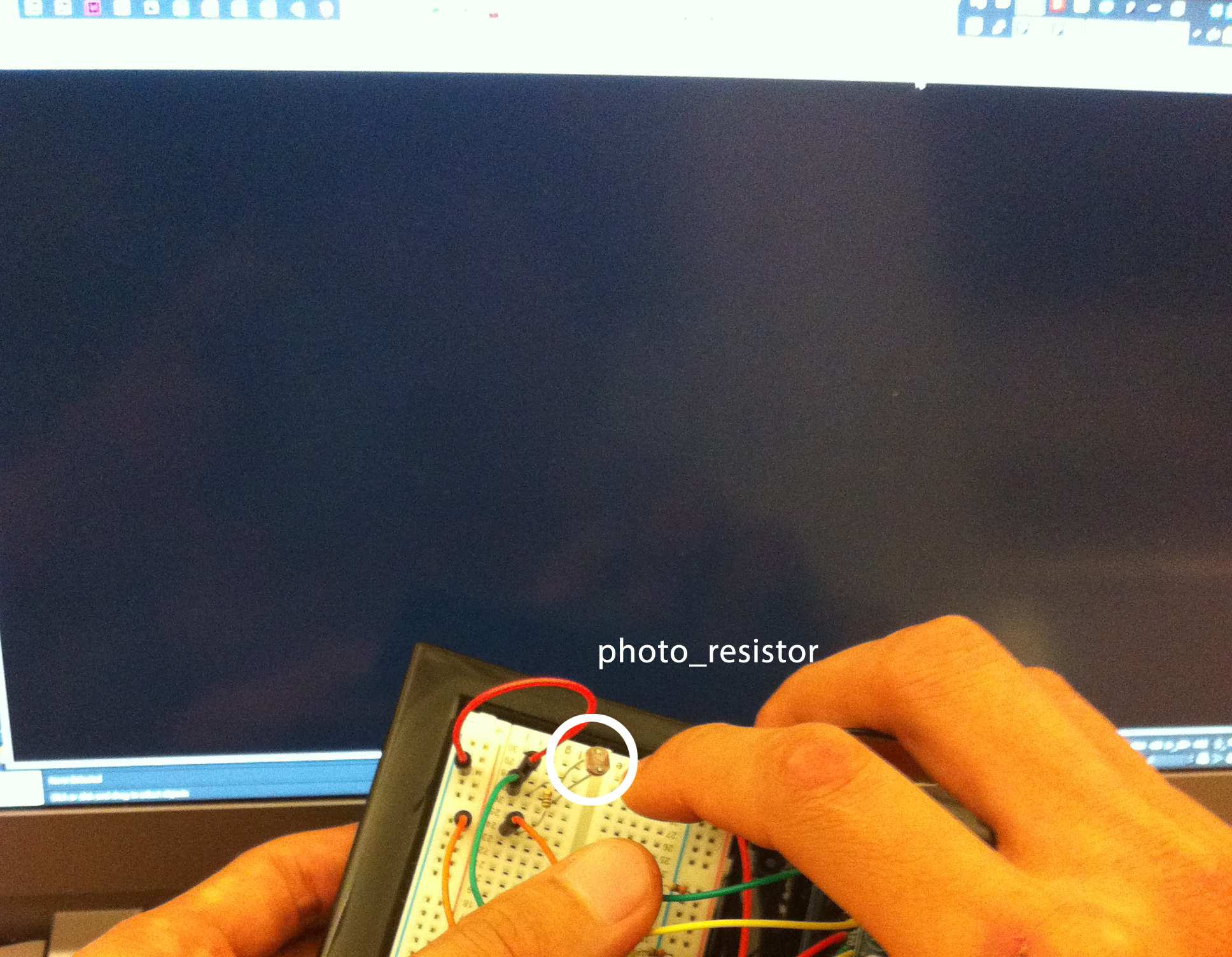 Background color is affected by the Photo Resistor input from the Arduino board and is around the value of 50 (0, 255) in this example.
 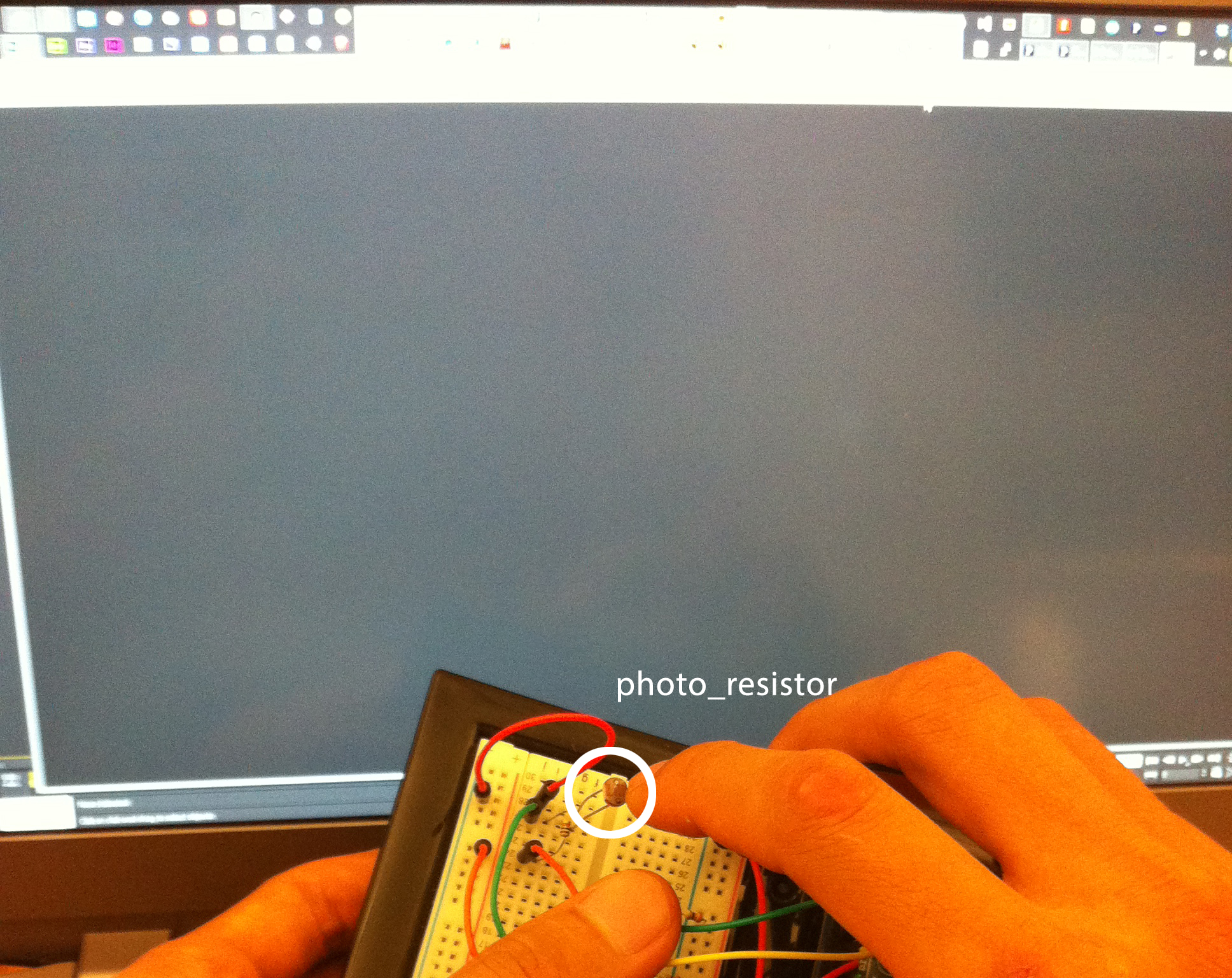 Background color is affected by the Photo Resistor input from the Arduino board and is around the value of 50 (0, 255) in this example.
 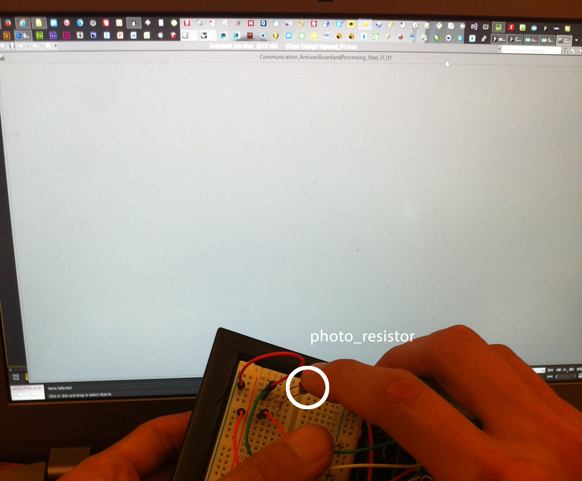 Background color is affected by the Photo Resistor input from the Arduino board and is around the value of 50 (0, 255) in this example
 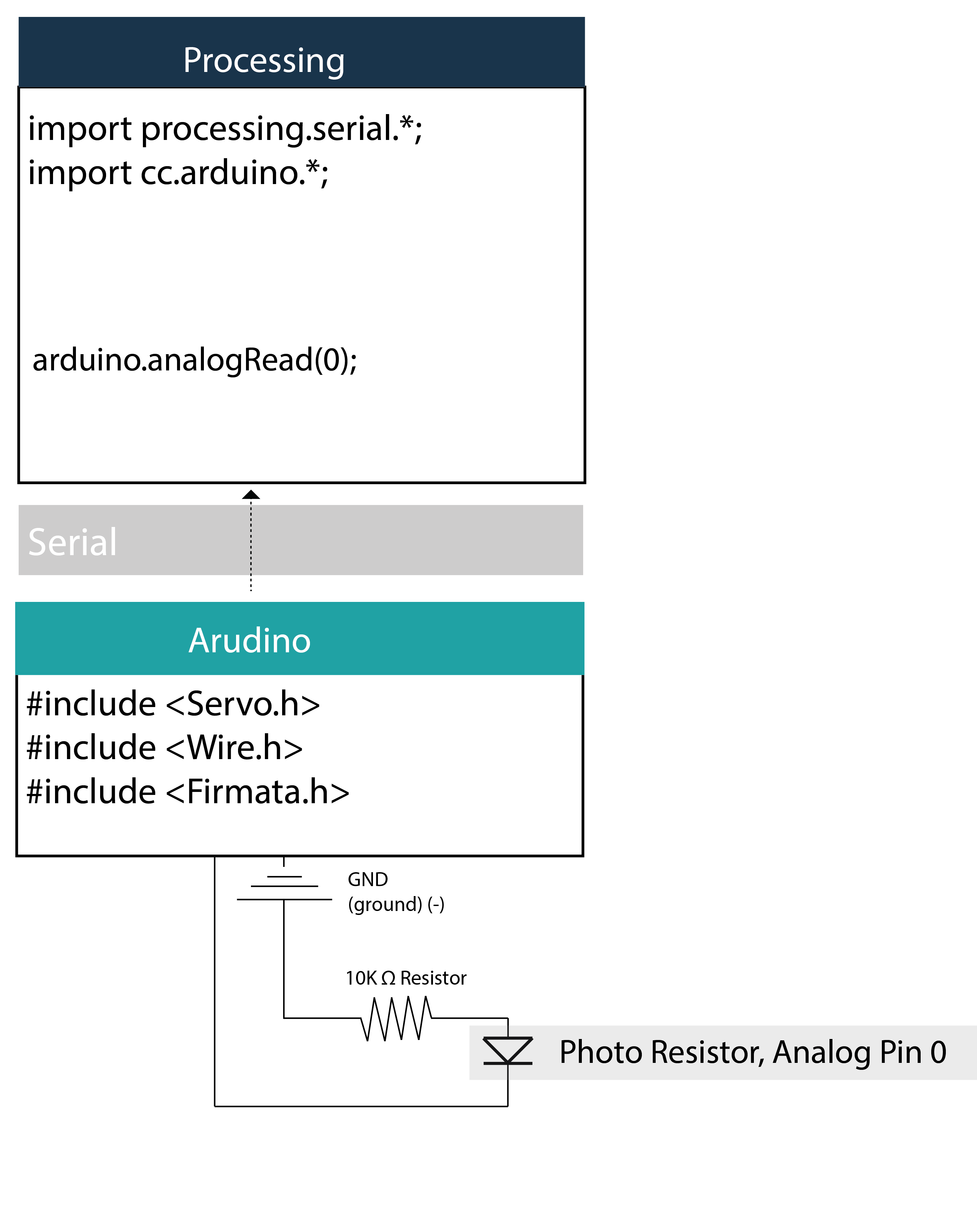 Documentation of cc.arduino library (link http://playground.arduino.cc/Interfacing/Processing) Arduino.list(): returns a list of the available serial devices. If your Arduino board is connected to the computer when you call this function, its device will be in the list.
Arduino(parent, name, rate): create an Arduino object. Parent should be “this” (without the quotes); name is the name of the serial device (i.e. one of the names returned by Arduino.list()); rate is the speed of the connection (typically 57600). Note that in the v2 library, the rate parameter is optional.
pinMode(pin, mode): set a digital pin to input, output, or servo mode (Arduino.INPUT, Arduino.OUTPUT, or Arduino.SERVO). digitalRead(pin): returns the value of a digital pin, either Arduino.LOW or Arduino.HIGH (the pin must be set as an input). digitalWrite(pin, value): writes Arduino.LOW or Arduino.HIGH to a digital pin.
analogRead(pin): returns the value of an analog input (from 0 to 1023).
analogWrite(pin, value): writes an analog value (PWM wave) to a digital pin that supports it (pins 3, 5, 6, 9, 10, and 11); value should be from 0 (always off) to 255 (always on).
servoWrite(pin, value): writes a value to a servo motor; value should be from 0 to 180.
Reference
http://playground.arduino.cc/Interfacing/Processing https://processing.org