This tutorial will show how to identify the coordinates of the space encompassed by objects within a grid. By using two axes with evenly spaced PIR motion detectors, multiple moving objects can be identified. In addition, when multiple objects are close together in the space, the coordinates will include any area covered on two sides by the objects themselves.
Note: Although this tutorial will use 3 total PIR detectors, the number of sensors can be expanded for larger grids with minimal changes to the code.
Behavior:
Figure A: Gridded PIR Sensor System
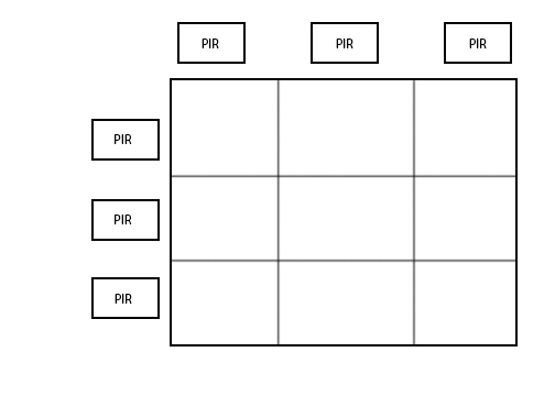
The gridded PIR sensors should be set up as shown in Figure A. In the next few diagrams, the circles represent objects in the grid, and the X’s represent the squares whose coordinates will be returned by Arduino via the serial cable. The red lines show which PIR sensors are set off by the objects.
Figure B: One Object Detected
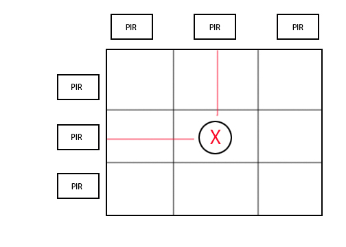
If one object is present in the grid, it will set off PIR sensors attached to the closest column and the closest row.
Figure C: Two objects detected in a line
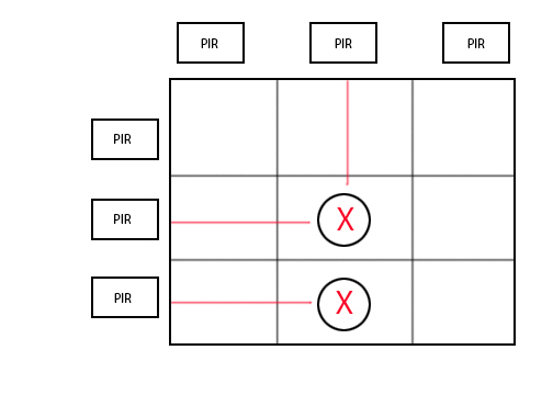
If two objects in a straight horizontal/vertical line are detected, each object will be detected and the coordinates returned will only be those where the objects are located.
Figure D: Three objects detected (not in a line)
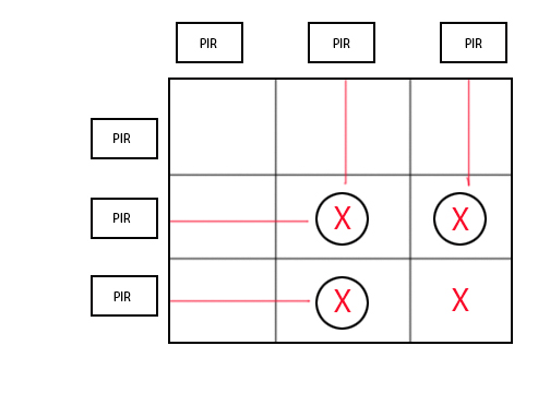
If the objects encompass a certain area on two sides (e.g. if a group of people is walking through a gridded area), the space that they enclose will also be returned as a coordinate value.
This will allow for the response to change when a group enters the space. If the group is neatly ordered in a straight line, the returned coordinates will similarly reflect a straight line. However, if the group is disorderly and spread out in the space, the returned coordinates will reflect the total area encompassed by the group.
Figure E: Objects Along a Diagonal Line

If the objects are placed along the entire diagonal, then all possible coordinates will be returned. According to the initial behavior, each returned value should be encompassed on two sides. In the diagonal case with all coordinate pairs returned, this is technically true, but some of the squares will be two squares or more removed from the actual object, which may encompass more space than desired. In order to fix this problem, additional sensors, such as force sensors on squares outside the diagonal, will provide enough input to double check the presence of objects in those areas.
This is an optional addition, but for our purposes, we will be focusing only on the PIR motion sensors in this tutorial.
Parts Required:
1x Arduino Uno
1x Breadboard
PIR Motion Sensors (one per mark on either axis forming the grid; for example, if the x-axis has 3 marks and the y-axis has 2 marks, then 5 total sensors are needed)
Assorted wires with headers (2x to bring power to the breadboard, 3x for the ground, 5V, and output on each PIR sensor)
Circuit Diagram :
Note: These are examples from a situation with 3 PIR Motion Sensors (1 row and 2 column); if adding more sensors, the wiring will be the same except additional sensors would connect into the digital inputs and the power (5V and Ground) rails on the breadboard.
Figure F: Breadboard diagram
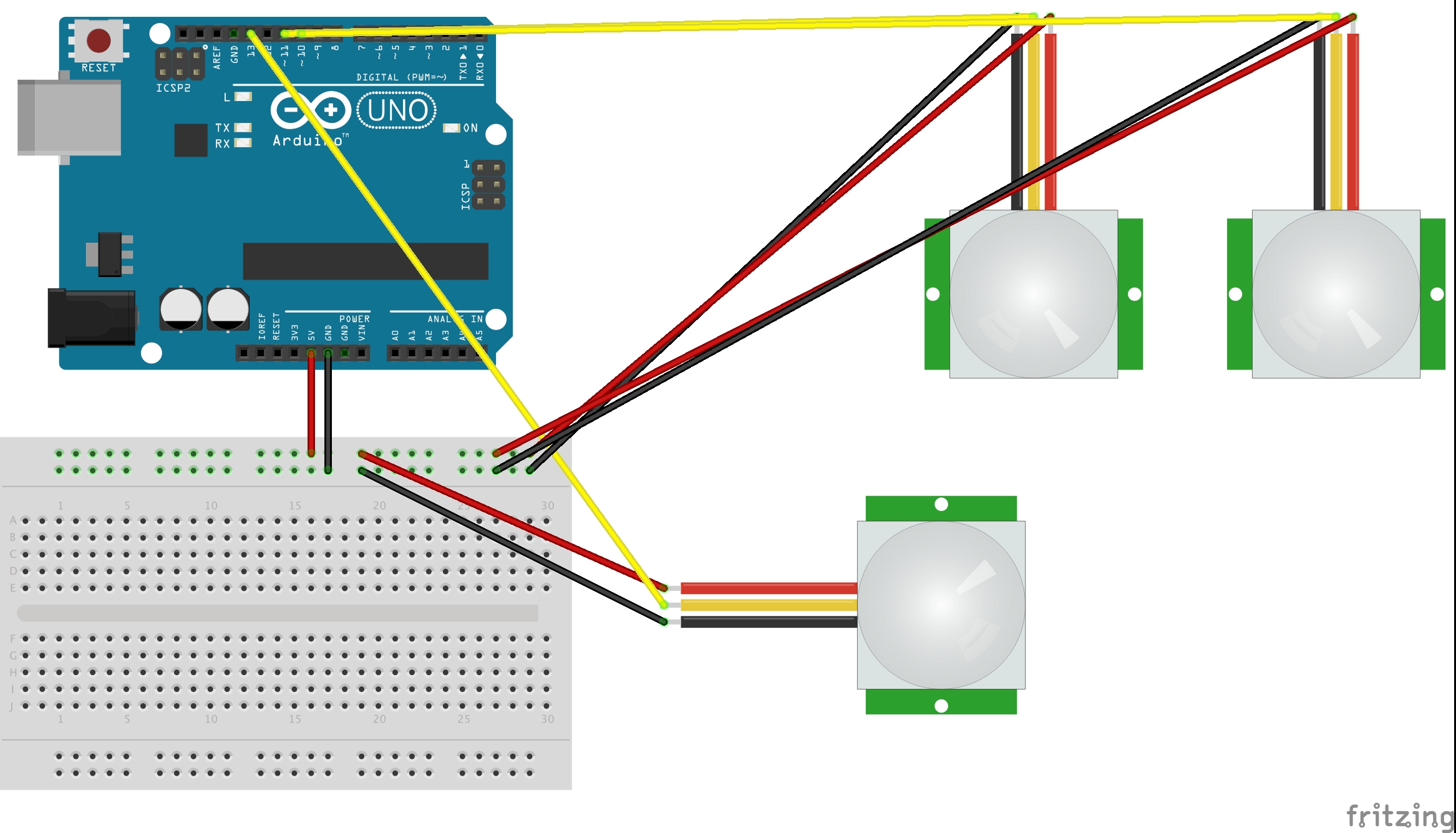
Figure G: PCB diagram
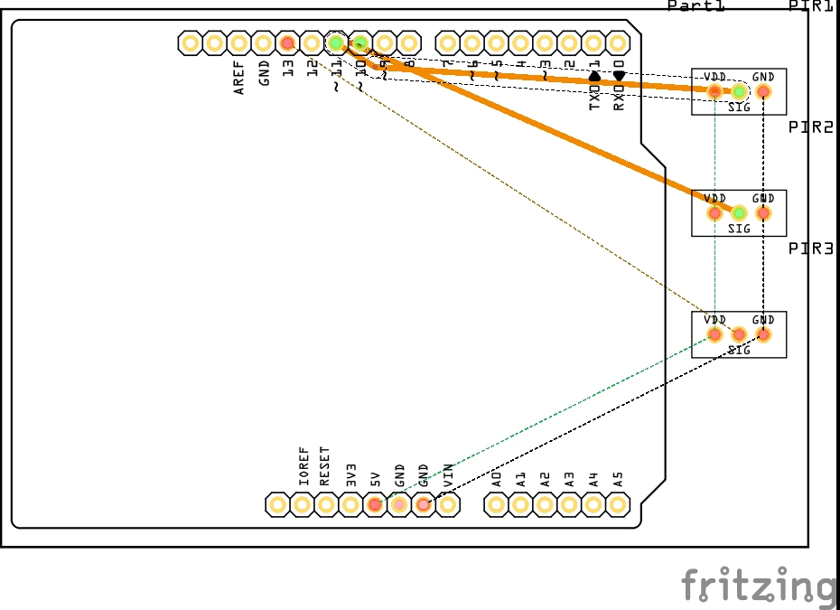
Figure H: Constructed Circuit
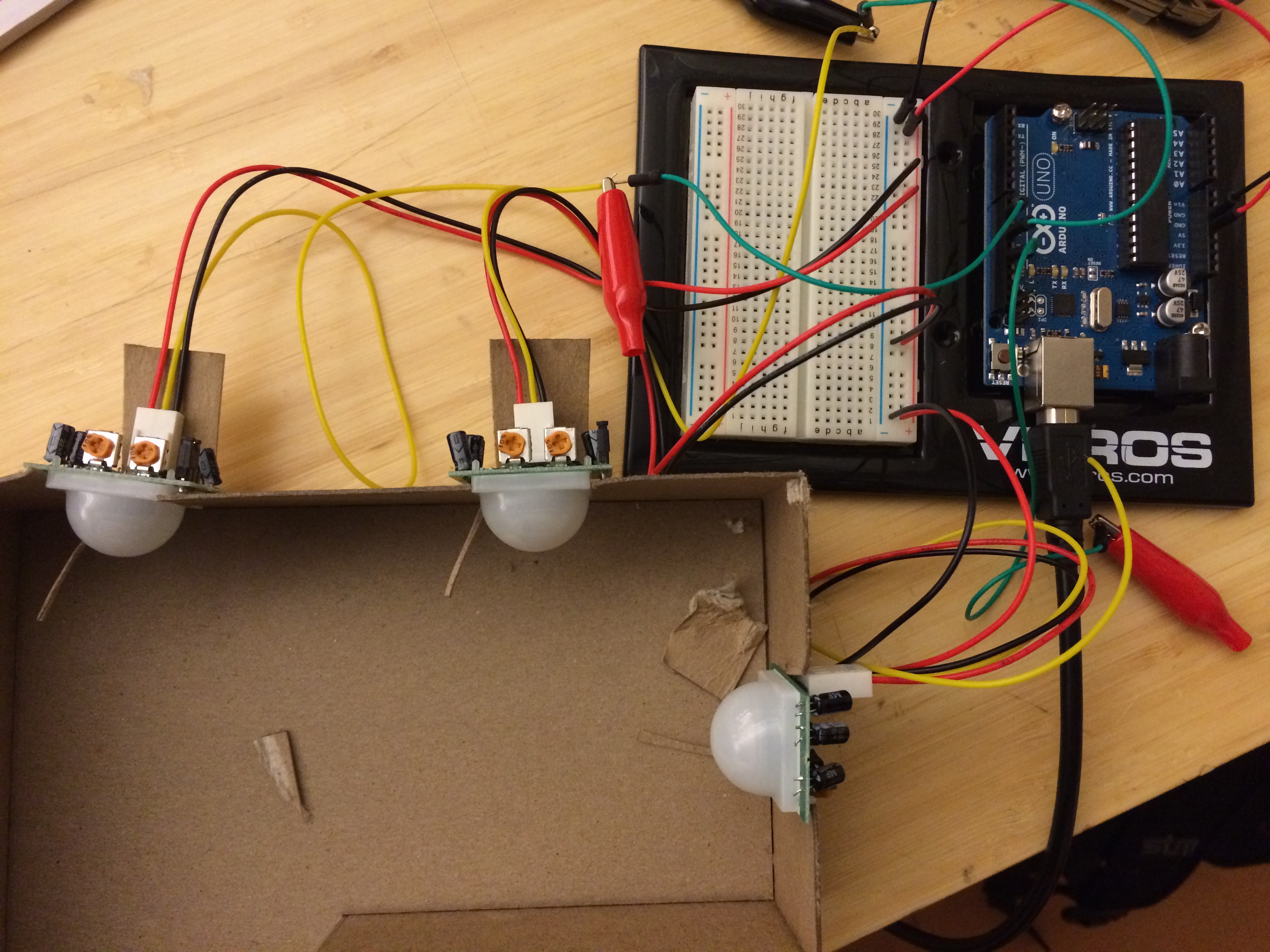
Figure F is most helpful in seeing what the wiring looks like when connecting the different sensors to the Arduino, while Figure G shows the simplified connections from each sensor to the individual pins on the board. Figure H is provided as an example of what an assembled circuit would look like (here, the alligator clips are used to connect wires to increase length–these are optional).
The exact pin that the output of the sensor goes to is unimportant, as long as the arrays storing pin values in the Arduino code are also changed to match the locations of the row and column pins.
Note: In Figures A and C, the sensors are shown pointed in the correct direction, although the spacing would be much further apart in a finished project (Remember, the sensors can detect motion up to 20 feet away!).
Arduino Code:
Variables:
Here the variables initialized are used to keep track of the pins in each row and column, the number of pins in rows and columns, and the value read from each pin. Arrays are used to keep track of pins and their values so that the value of each sensor can be iterated through using a for loop later on in the code. The rowInputPinCount and columnInputPinCount help this for loop count up to the total number of pins. As an example, row number 0 would correspond to pin number 13.
Change PinCount variables and the values in the array to accommodate for more sensors added in. For example, if you added in a row sensor at pin 5, the rowInputPin would need a 5 at the end, the rowInputPinCount would be raised to 2, and the rowVal array would need another 0 at the end.
Setup:
|
1 2 3 4 5 6 7 8 9 |
void setup() { for (int thisPin = 0; thisPin < rowInputPinCount; thisPin++) { pinMode(rowInputPin[thisPin], INPUT); } for (int thisPin = 0; thisPin < columnInputPinCount; thisPin++) { pinMode(columnInputPin[thisPin], INPUT); } //each for loop declares all the row and column pins, respectively, as inputs Serial.begin(9600); |
Each for loop is used to declare all the pins that measure movement in the rows or columns into INPUT pins. In addition, the setup initializes the serial monitor to begin communication–this can later be hooked up into Processing or read on a screen for human input.
Loop:
|
1 2 3 4 5 6 7 8 |
void loop(){ for (int thisPin = 0; thisPin < columnInputPinCount; thisPin++) { colVal[thisPin]=digitalRead(columnInputPin[thisPin]); } for (int thisPin = 0; thisPin < rowInputPinCount; thisPin++) { rowVal[thisPin]=digitalRead(rowInputPin[thisPin]); } //use for loop to take a reading of each column and row input pin |
The loop starts off with two for statements that take in the readings from each PIR sensor and store them in either the array for row sensors or column sensors depending on the PIR location.
This enables later code to use one index number to find both the PIR sensor’s pin and the value from that pin.
|
1 2 3 4 5 6 7 8 9 10 11 12 13 14 15 16 17 18 19 |
for (int thisColPin = 0; thisColPin < columnInputPinCount; thisColPin++) { //this for loop runs through each column pin if (colVal[thisColPin]==HIGH) { //if motion in the column is detected, then each row in the column is checked for (int thisRowPin = 0; thisRowPin < rowInputPinCount; thisRowPin++) { //this for loop runs through each row pin if (rowVal[thisRowPin]==HIGH) { //if the row pin has detected motion //Serial.print("Motion Detected! Column:"); Serial.print(thisColPin); Serial.print( ","); //Serial.print("Row: "); //Uncomment the serial.print commands for a more human-readable format Serial.println(thisRowPin); //coordinates of motion are printed out to the serial monitor } } } } |
This part of the code looks daunting at first, but it’s essentially nested for loops that check every coordinate in the grid. If both the column and the row pin detected motion, then the coordinate corresponding to that row number and that grid number are printed out.
In the code itself, you can uncomment certain lines to make the output easier to read in the serial monitor. Alternatively, leaving the code as is will make it easier to send to an outside program such as Processing.
The first for loop runs through a check of each of the column pins and then runs them through an if statement to check if any of them detected motion. If so, then the next for loop runs through every row pin to see if it detected motion. If at any point, a row sensor and a column sensor both detect motion, then the coordinate of that point is then printed to the serial monitor.
Variables rowInputPinCount and columnInputPinCount ensure that the for loops do not exceed the number of entries in the arrays that store the pin values for the row and column pins.
Note: If the coordinates outputted don’t match the ones that you have assigned to the rows/columns, then check to make sure the pins are entered in the correct order on the rowInputPin and columnInputPin arrays. If the order of sensors is switched, then the coordinates will be incorrect.
Output:
Figure I: Serial Monitor Output
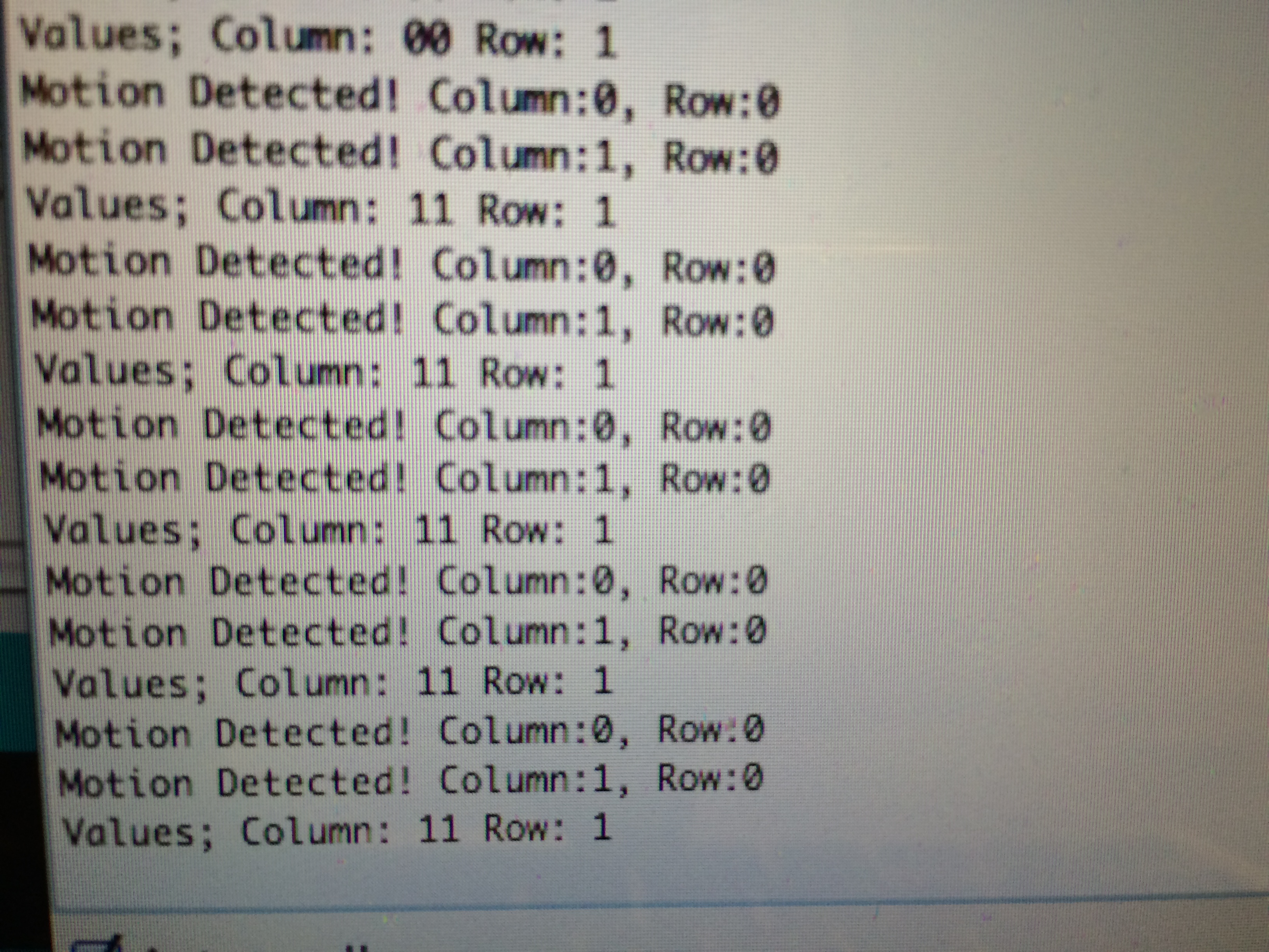
When the PIR sensors in the row alone detect movement, no motion is registered (in the first line, each of the column sensor values are 0, indicating lack of change).
As soon as motion is detected in the columns as well as the row, then the serial output changes. Since the system has confirmation that multiple sensors are seeing a change, motion is registered and the coordinates that it covers are outputted to the monitor.
Currently, the PIR sensor is set to retriggering mode–it will output a constant value as long as the obstruction is present. The sensitivity can be adjusted by turning the orange knob at the back counterclockwise (to reduce sensitivity), as well as by changing the position of the jumper (which will make it non-retriggering–registering motion only once, as opposed to continuously for the duration of its presence in front of the sensor). A guide on how to adjust these two aspects is found here (https://learn.adafruit.com/pir-passive-infrared-proximity-motion-sensor/testing-a-pir).
Full Arduino Code:
|
1 2 3 4 5 6 7 8 9 10 11 12 13 14 15 16 17 18 19 20 21 22 23 24 25 26 27 28 29 30 31 32 33 34 35 36 37 38 39 40 41 42 43 44 45 46 47 48 49 50 51 52 53 54 55 56 57 58 59 60 61 62 63 64 65 66 67 68 69 70 71 72 73 74 75 |
/* MotionSensorGrid This sketch enables a grid system of PIR motion detectors on two axes to output coordinates on the grid defining areas that objects encompass. The circuit: * PIR sensors on each input pin equivalent to total marks on both axes * Output to serial monitor (to be later taken in by Processing or by output method of choice) Created 2014-11-11 By Tanay Nandgaonkar Adapted from https://learn.adafruit.com/pir-passive-infrared-proximity-motion-sensor/using-a-pir */ int rowInputPinCount=1; // the number of row marks int columnInputPinCount=2; // the number of column marks int rowInputPin[] = {13}; // the ordered row input pins (for PIR sensor) int columnInputPin[] = {11,9}; // the ordered column input pins (for PIR sensor) int rowVal[] = {0}; // array for reading the row pins' status int colVal[] = {0,0}; // array for reading the column pins' status void setup() { for (int thisPin = 0; thisPin < rowInputPinCount; thisPin++) { pinMode(rowInputPin[thisPin], INPUT); } for (int thisPin = 0; thisPin < columnInputPinCount; thisPin++) { pinMode(columnInputPin[thisPin], INPUT); } //each for loop declares all the row and column pins, respectively, as inputs Serial.begin(9600); } void loop(){ for (int thisPin = 0; thisPin < columnInputPinCount; thisPin++) { colVal[thisPin]=digitalRead(columnInputPin[thisPin]); } for (int thisPin = 0; thisPin < rowInputPinCount; thisPin++) { rowVal[thisPin]=digitalRead(rowInputPin[thisPin]); } //use for loop to take a reading of each column and row input pin for (int thisColPin = 0; thisColPin < columnInputPinCount; thisColPin++) { //this for loop runs through each column pin if (colVal[thisColPin]==HIGH) { //if motion in the column is detected, then each row in the column is checked for (int thisRowPin = 0; thisRowPin < rowInputPinCount; thisRowPin++) { //this for loop runs through each row pin if (rowVal[thisRowPin]==HIGH) { //if the row pin has detected motion //Serial.print("Motion Detected! Column:"); Serial.print(thisColPin); Serial.print( ","); //Serial.print("Row: "); //Uncomment the serial.print commands for a more human-readable format Serial.println(thisRowPin); //coordinates of motion are printed out to the serial monitor } } } } //Uncomment this block of code to see the values of the pins by column and row // Serial.print("Values; Column: "); // for (int thisPin = 0; thisPin < columnInputPinCount; thisPin++) { // Serial.print(colVal[thisPin]); // } // Serial.print(" Row: "); // for (int thisPin = 0; thisPin < rowInputPinCount; thisPin++) { // Serial.println(rowVal[thisPin]); // } delay(1000); } |