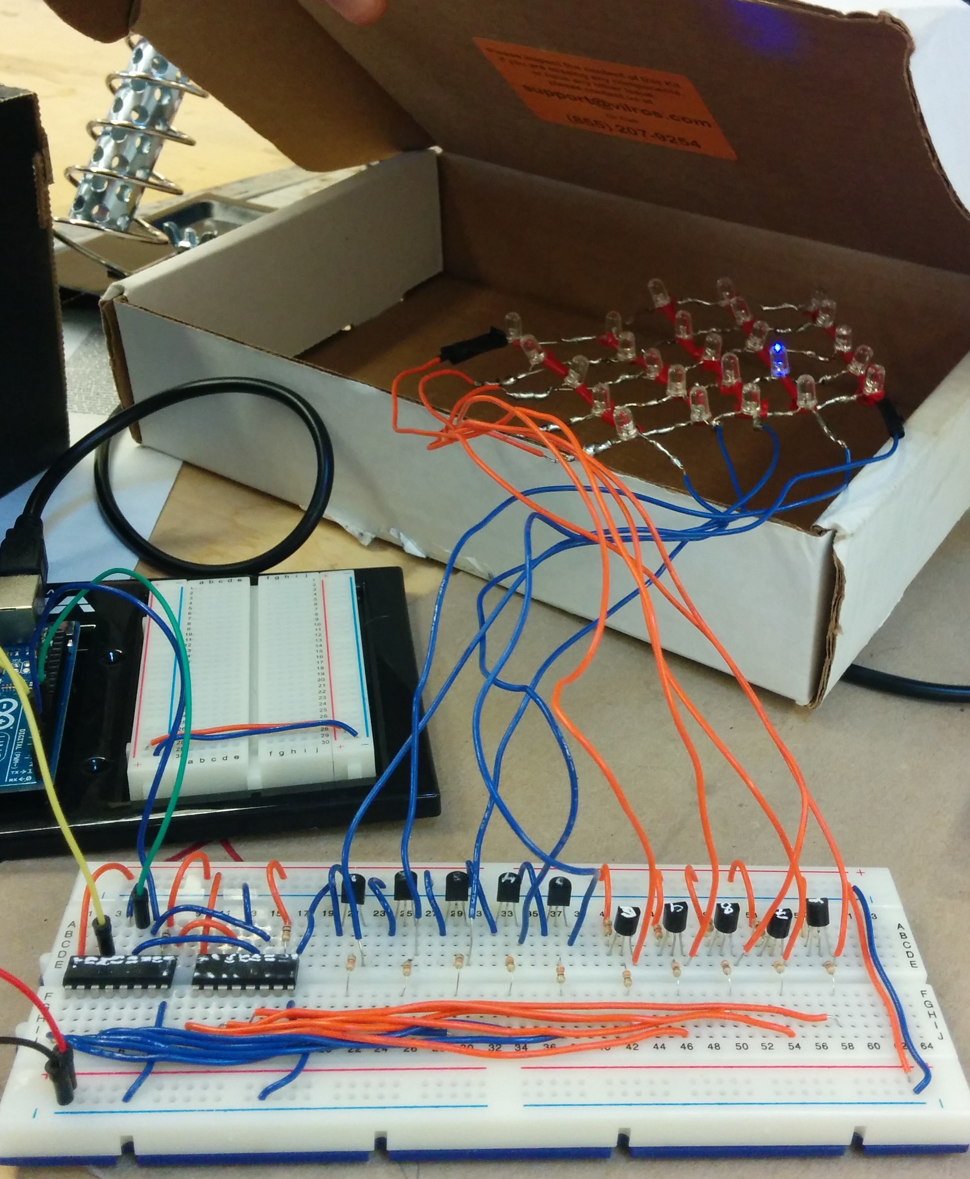
This tutorial will cover the basic knowledge you need to hack your way at a self-made LED matrix. We will use open source instructions available online from various groups to learn about the components of this kind of project and to acquire code to control the LED matrix. Various sources for each of the components will be given. As will become apparent, there are many ways to solve a circuitry problem. Our main “problem” when making a 5X5 LED matrix is the limited number of Arduino output pins we have to control it. In this tutorial we will be controlling 25 LEDs using Shift registers and NpN transistors to minimize the number of Arduino pins needed to control the lights.
Your needed materials are:
– 1 Arduino Uno
– 2 Shift registers (I use 74HC5950)
– 10 NPN transistors (BC547)
– 5 1kohm resistors (for base of transistors)
– 10 100 ohm resistors (for the emitters of the transistors)
– 25 LEDs ( I use blue)
– Lots of wire
– Solder and soldering iron
We will start by watching a video that covers the basics. [ VIDEO: https://www.youtube.com/watch?v=GPokkuX_jjk ]
The main concepts from the Make video by Collin Cunningham are:
• LED matrix ( powering and controlling LEDs through columns & rows)
• How to bend the anode and cathode legs to create LEDs in parallel to create your own matrix
• Multiplexing using a serial LED display driver
Collin Cunningham gets fancy and uses an already build LED matrix and even makes his own printed circuit board. In order to lower costs we will be using some different methods to multiplex, but this video is by a charismatic character who quickly shows the process.
The initial inspiration for the configuration used in this tutorial comes from instructables.com by user Osgeld. [ HACK: http://www.instructables.com/id/The-74HC164-Shift-Register-and-your-Arduino/?ALLSTEPS ] The user goes through 3 possible projects using Arduino and Shift registers. The third project is the matrix controlled by using a shift register and transistors. He provides code for this configuration, which is always nice. The following two figures show the logic and circuitry behind the hardware.
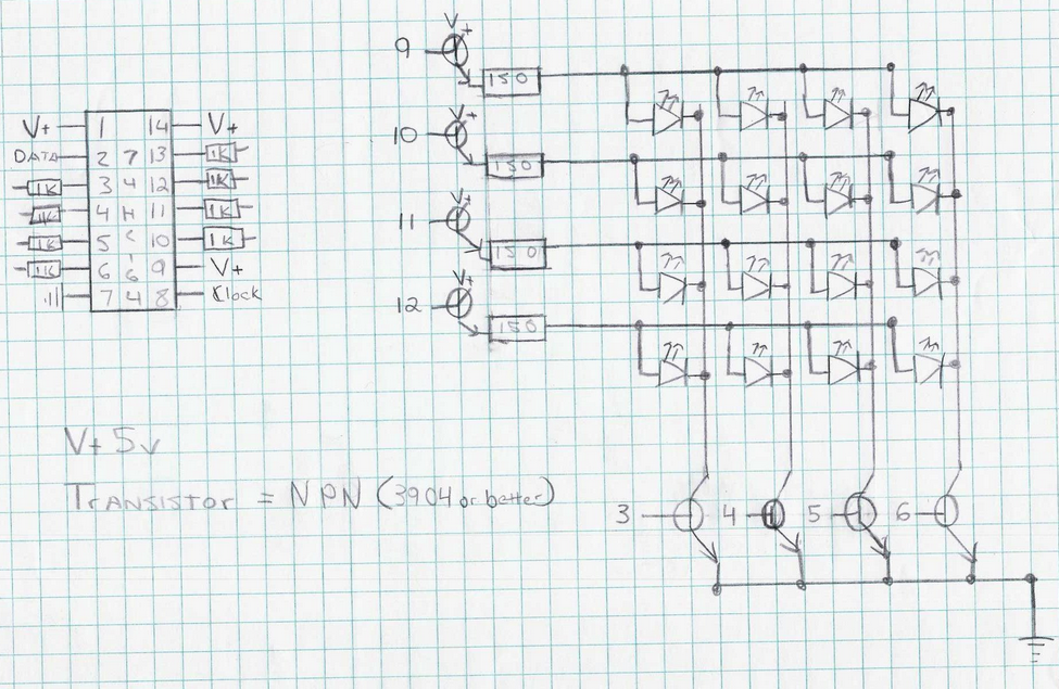
Figure 2 Circuit by Osgeld on the Instructables page
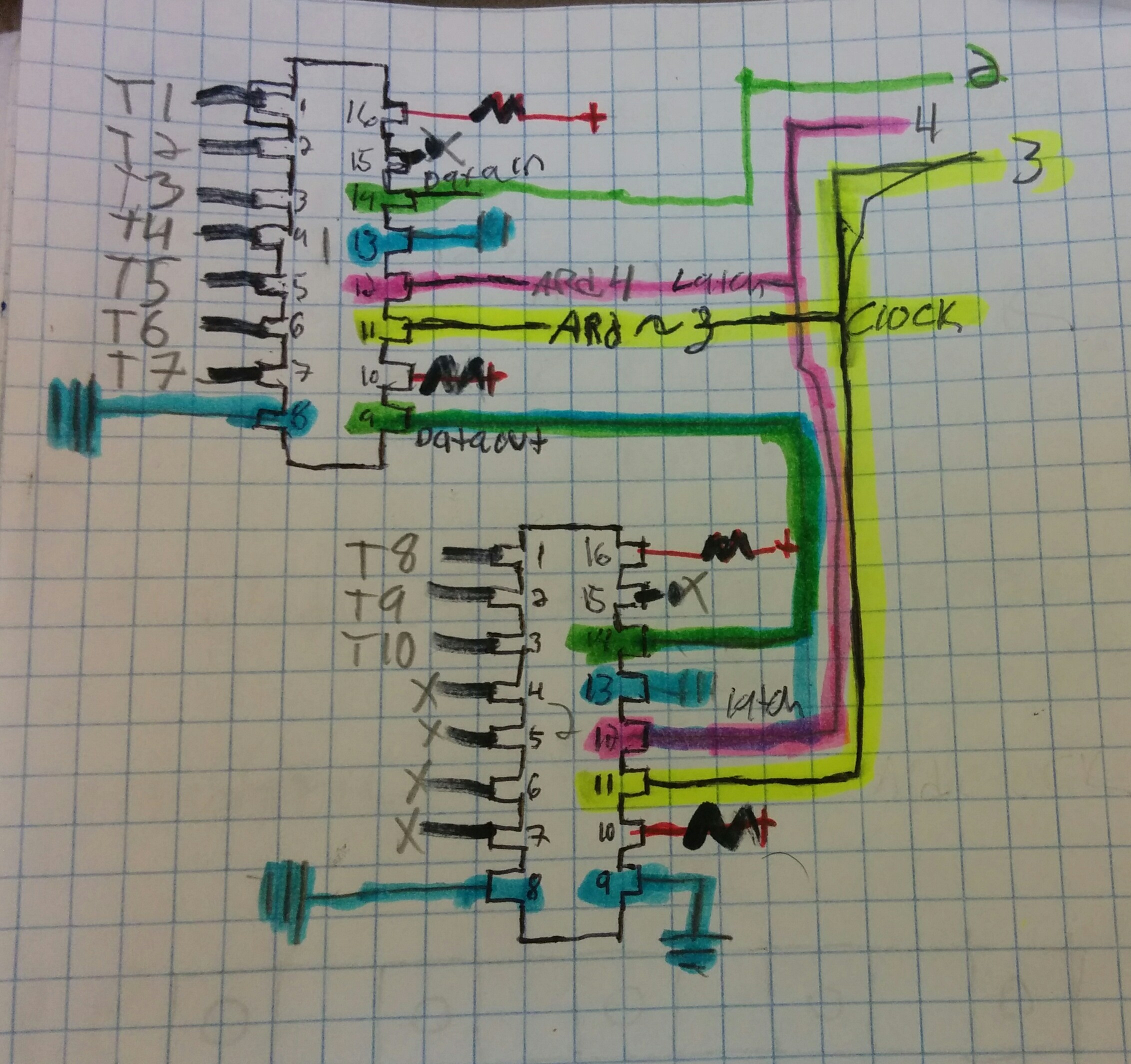
Figure 3 It is helpful to have a circuit diagram to help you as you wire
YouTube user Andrew Ong produced a great video that shows his digital model of a similar configuration. [ VIDEO: https://www.youtube.com/watch?v=2m3PbCvcqkY ] He points out the importance of choosing the right components to avoid a dimming effect and explains how the signal moves through the circuit.
If you work well with text this online Arduino workshop has a good explanation of LED matrices. http://www.thebox.myzen.co.uk/Workshop/LED_Matrix.html
As you can see there are 5 components to this project: the Arduino, shift registers, transistors, LEDs, and of course resistors. We already know about the Arduino, so we need to give homage to electrical engineers and watch some videos that explain the necessary components needed to multiplex with LEDs. The videos will explain (in varying depth) the uses, coding, and mechanism behind each component. It is helpful to have the data sheets of the components you are using while watching these videos. You should also pay attention to the symbols they use when drawing the circuits, it will help you learn how to interpret circuit diagrams for future projects.
LEDs and resistors:
EEEnthusiast is a user of YouTube, he produces very thorough explanations on electrical topics. His video “Arduino Tutorial #1 – Extended – Limitations I/O pins, Pull-down, Current Resistor Calculations” explains current resistor calculations with Arduino.(https://www.youtube.com/watch?v=gGDq_-WKMfE&list=UU6JpBeS_6JhUwfGF8RgLCIQ)
A great follow up is “Resistance for LEDs Tutorial” by YouTube user Kevin Darrah. He explains the calculations needed to choose a resistor for your LEDs, although you use the same principle to calculate for other components as well. If you need additional help understanding resistors he has several other videos explaining their use and he points out the different symbols used when drawing circuits. When you are ready, he also has instructions on building other fun things like LED cubes. (https://www.youtube.com/watch?v=7PzohqhABj4)
When you are ready to calculate the resistant using Ohms law, there are handy websites (like http://www.ohmslawcalculator.com/led_resistor_calculator.php ) that can help you.
Transistors
Kevin Darrah also has a video explaining multiplexing LEDs with transistors that explains the hardware and software for controlling a matrix. https://www.youtube.com/watch?v=lZyc6ulpkyM There are may other videos that explain transistors, I recommend other by EEEnthusiast and Kevin Darrah such as:
‘How to work with Transistors’ by Kevin Darrah: https://www.youtube.com/watch?v=6RN1hnwBj3Y
‘How to Multiplex/ Part II’ by Kevin Darrah: https://www.youtube.com/watch?v=-1UPPHjR0vk&src_vid=lZyc6ulpkyM&feature=iv&annotation_id=annotation_397974
He explains why you use resistors on transistors, and how to multiplex the transistors to control the cathode and anode columns and rows.
‘Arduino #11 – High Current & Voltage Loads Tutorial – Transistors and Relays’ by EEEnthusiast (IF you are working with components that need higher voltage): https://www.youtube.com/watch?v=JJB_ICWYIqg&list=UU6JpBeS_6JhUwfGF8RgLCIQ
GarageLabe.com posted a tutorial on an 8×8 matrix that gives the best explanation on using transistors to create the persistence of vision effect that allows us to multiplex LEDs. It goes through the logic of coding for LEDs in parallel. The post also contains the basic layout of code to control a matrix using transistors. http://garagelab.com/profiles/blogs/arduino-scrolling-text-marquee-to-give-a-happy-christmas
Shift registers
The shift registers in the 5X5 matrix we want to build will allow us to control all 25 LEDs from 3 pins on Arduino. The 74HC595 is an integrated circuit that has 8 outputs, we need two of them because we have 10 transistors that will need to be connected to it. The transistors themselves are each connected to a row or column controlling 5 LEDs. You can also get some shift registers that have many inputs if what you need for a project are additional ins.
‘Arduino Tutorial #3 – Shift Registers (74HC595)’ by EEEnthusiast has a thorough explanation of coding for shift registers as well as the configuration for the 74HC595 model https://www.youtube.com/watch?v=bqfPZXEuyuc
Need more? Try:
74HC595 Shift Register Control | AVR Tutorial by 000Plasma000 https://www.youtube.com/watch?v=d7Au3I4ZdZc
‘Multiplexing with Arduino and the 74HC595’ by amandaghassaei
http://www.instructables.com/id/Multiplexing-with-Arduino-and-the-74HC595/step2/How-does-the-74HC595-work/
A very similar circuit and code that is easily adapted
http://tronixstuff.com/2010/06/06/getting-started-with-arduino-chapter-nine/
Soldering
When building your own LED matrix it is important to solder the components appropriately. Watch this quick video by Collin Cunningham to get all the basics on soldering. https://www.youtube.com/watch?v=QKbJxytERvg
It is important when building a matrix that the row and column wires do not touch. This can be accomplished by using electrical tape to protect on of them from the other, as I have done. Alternatively, this can be accomplished by bending them appropriately to create a space between the two, as seen in this image from instructable.com
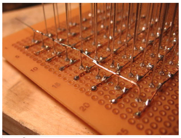
Figure 4 http://www.instructables.com/file/FLQPWTJFHAVXW8W
Now that you have your matrix built and connected test out your grid using test code. You will have to modify the code to match your wiring. I wanted to test the circuit so I adapted code from tronixstuff.com just to make sure the LEDs were getting power. For my matrix, one shift register controls cathodes and another the anodes
//// Modfied from http://tronixstuff.files.wordpress.com/2010/06/example9p1.pdf
int latchpin = 4; // connect to pin 12 on the ‘595
int clockpin = 3; // connect to pin 11 on the ‘595
int datapin = 2; // connect to pin 14 on the ‘595
int matrixrow[5] = {
1,2,4,8,16};
int matrixcolumn[5] = {
1,2,4,8,16};
void pixeldisplay(int row, int column, int holdtime)
// turns on and off a pixel at row, column – with delay ‘holdtime’
{
digitalWrite(latchpin, LOW);
shiftOut(datapin, clockpin, MSBFIRST, matrixcolumn[column-1]); // sets the digit to address
shiftOut(datapin, clockpin, MSBFIRST, matrixrow[row-1]); // clears the digit
digitalWrite(latchpin, HIGH);
delay(holdtime);
}
void rowdisplay(int row, int holdtime)
// turns on and off a row of LEDs with delay ‘holdtime’
{
digitalWrite(latchpin, LOW);
shiftOut(datapin, clockpin, MSBFIRST, 255); // we want all the cathodes on, which is 11111111 in binary, 255 decimal
shiftOut(datapin, clockpin, MSBFIRST, matrixrow[row-1]); // clears the digit
digitalWrite(latchpin, HIGH);
delay(holdtime);
}
void columndisplay(int column, int holdtime)
// turns on and off a column of LEDs with delay ‘holdtime’
{
digitalWrite(latchpin, LOW);
shiftOut(datapin, clockpin, MSBFIRST, matrixcolumn[column-1]);
shiftOut(datapin, clockpin, MSBFIRST, 255); // we want all the anodes on, which is 11111111 in binary, 255 decimal
digitalWrite(latchpin, HIGH);
delay(holdtime);
}
void setup()
{
pinMode(latchpin, OUTPUT);
pinMode(clockpin, OUTPUT);
pinMode(datapin, OUTPUT);
}
void loop()
{
for ( int a = 1; a < 10; a++) {
for ( int b = 1; b < 10; b++) {
pixeldisplay(a,b,50);
for ( int a = 1; a < 10; a++) {
for ( int b = 1; b < 10; b++) {
pixeldisplay(b,a,50);
} } } } }