This tutorial explains how to control a Servo’s angle of rotation in relation to a coordinate that can be found in a typical grid of points. You will need a(n):
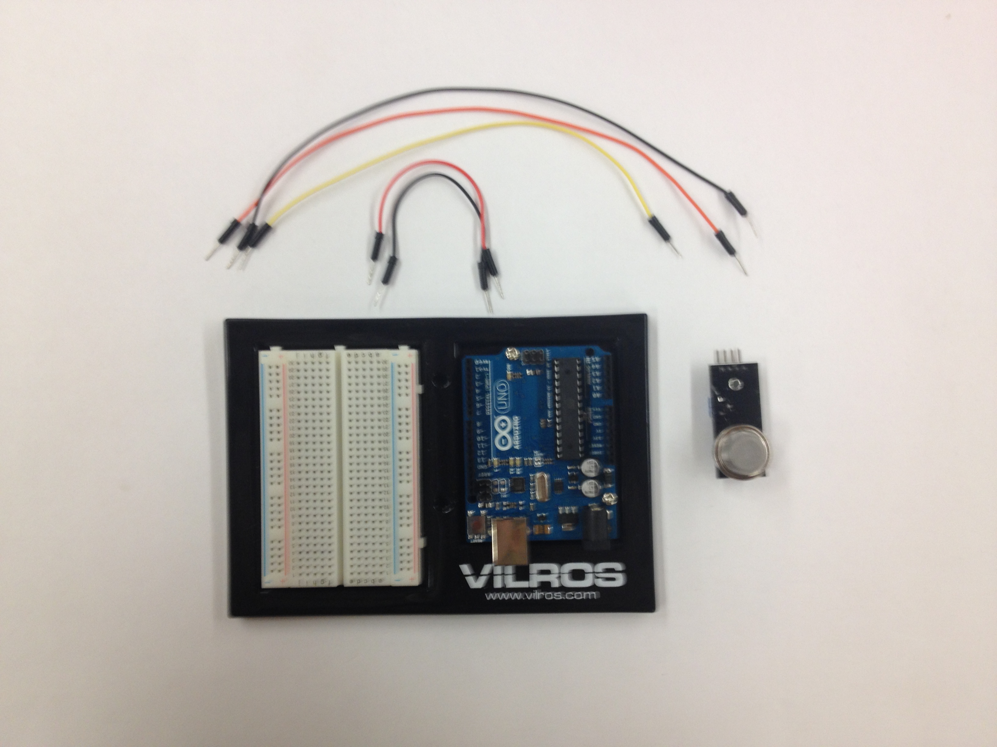
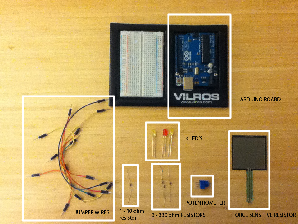
- Arduino Uno
- Breadboard
- Servo (that can rotate 360 degrees)
- 6 Wires
Setting It Up
Before we begin to put the parts together, make sure your Arduino board is not connected to your computer!
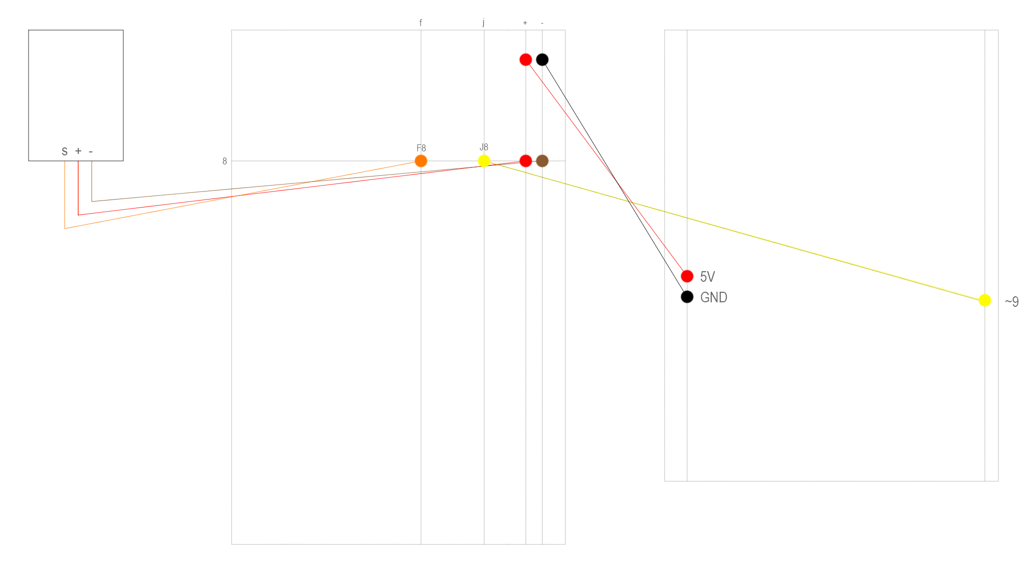
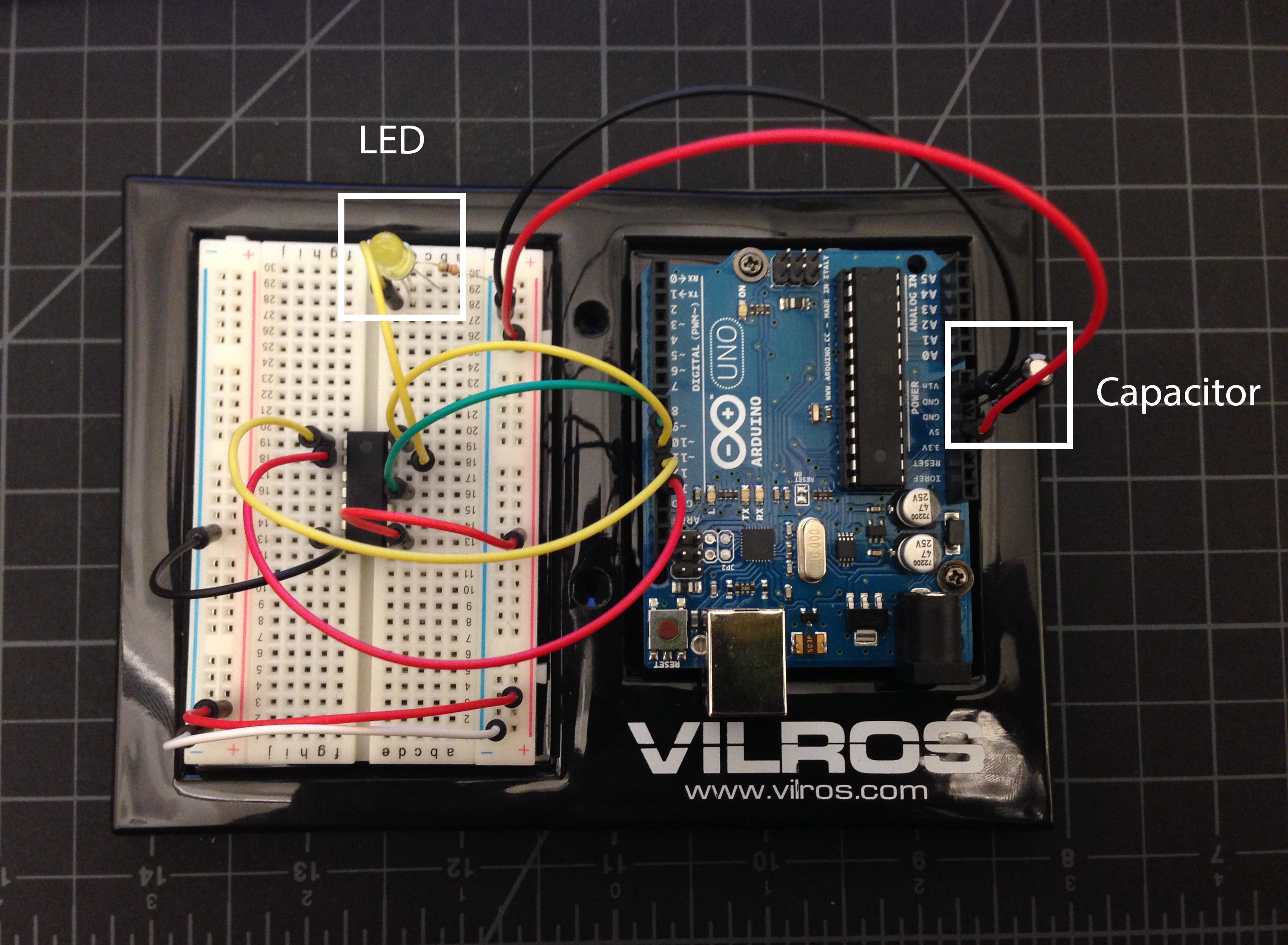
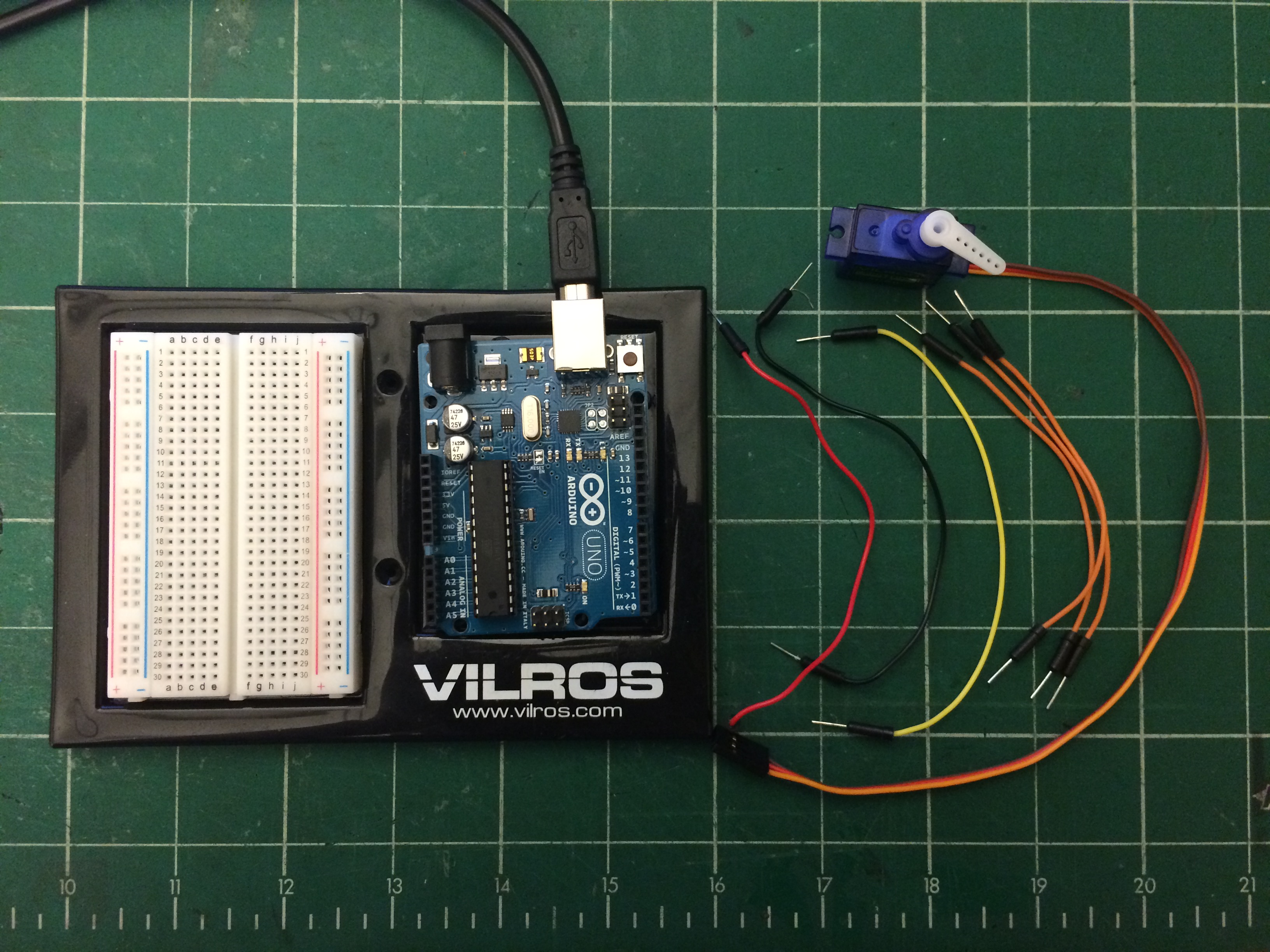
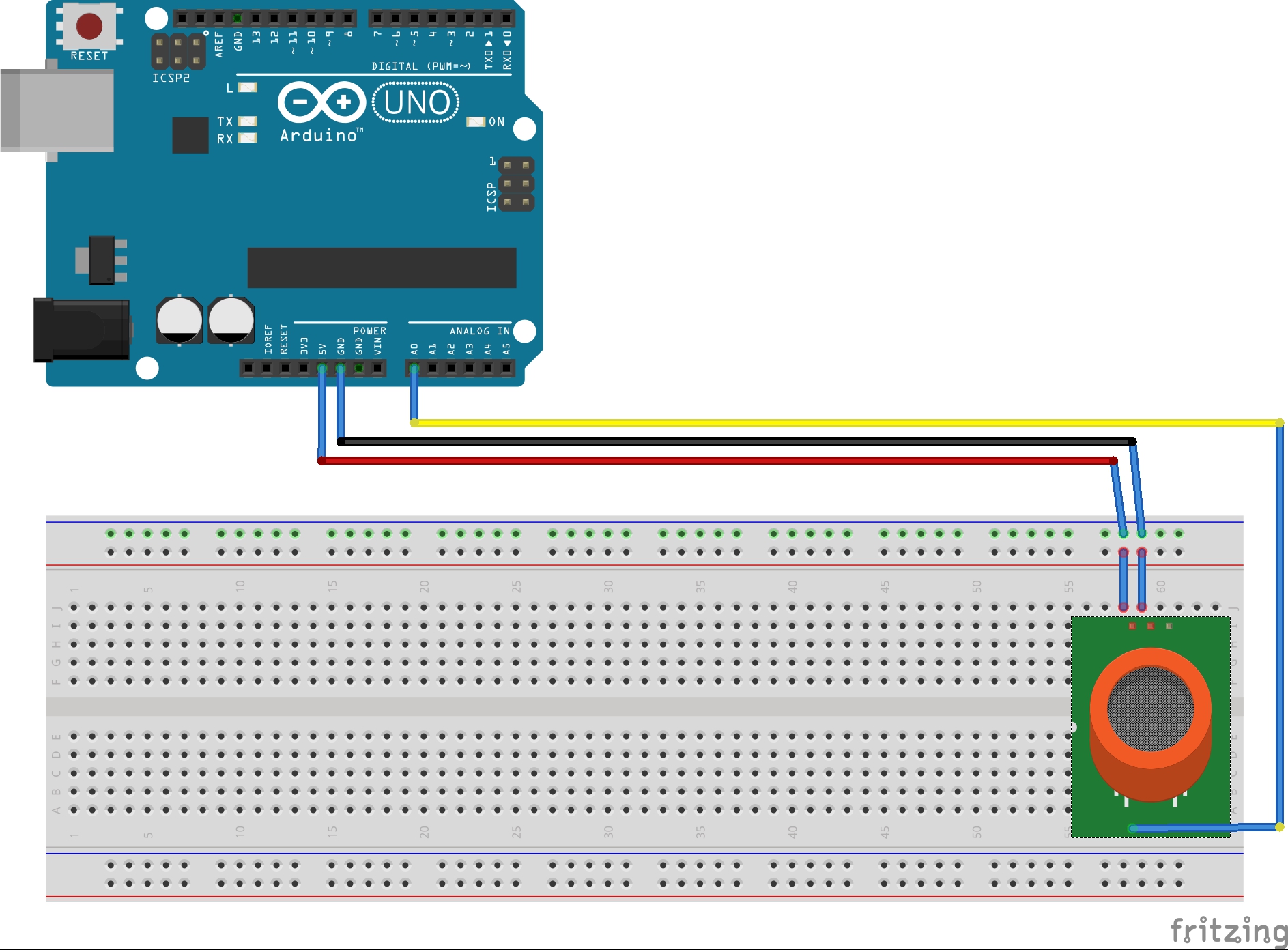
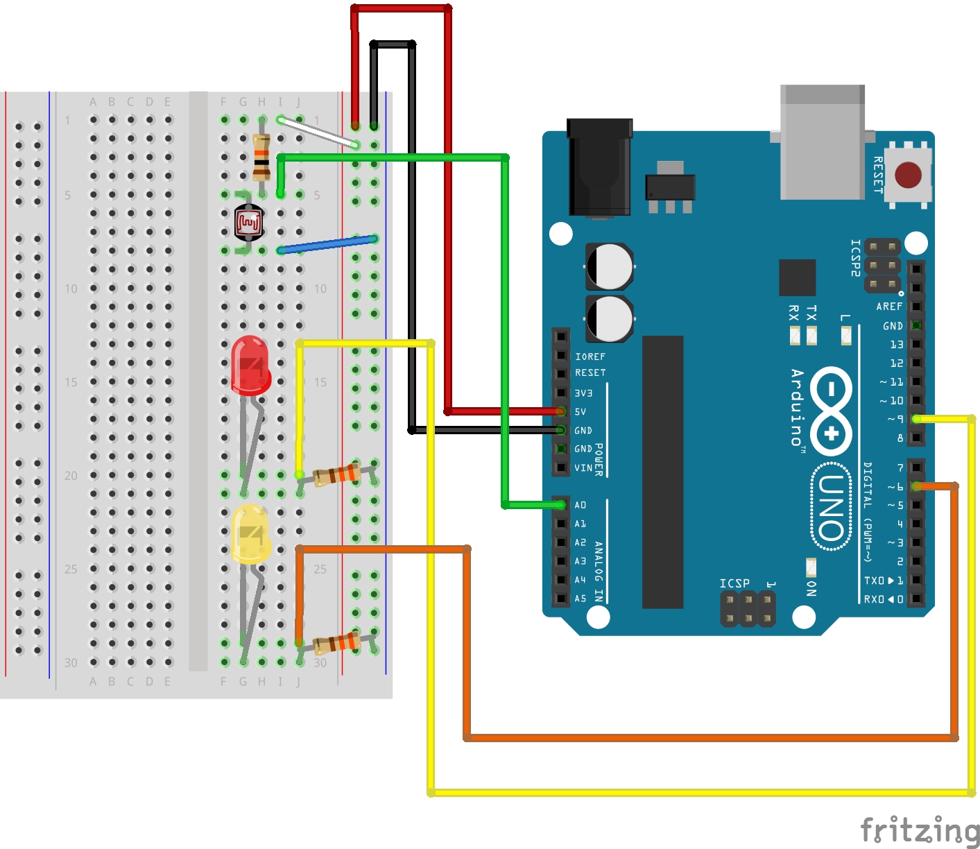
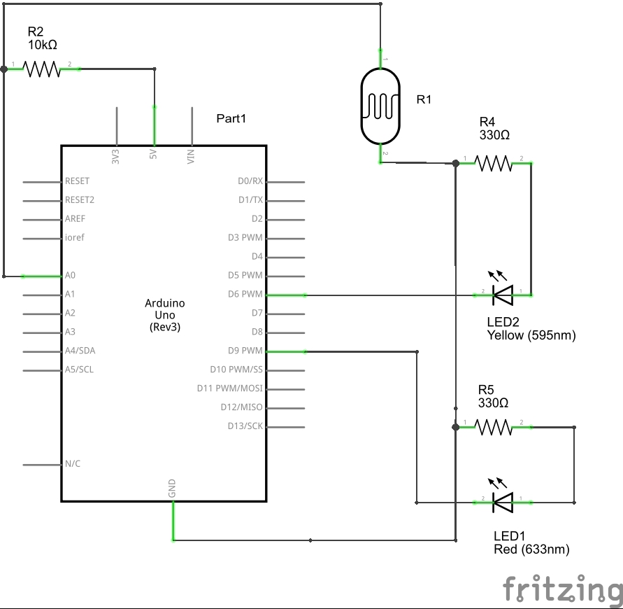
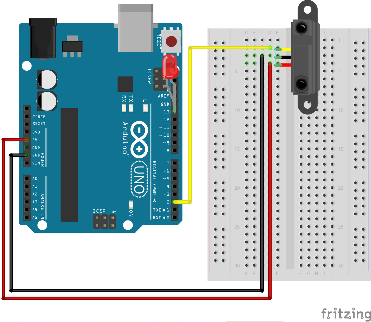
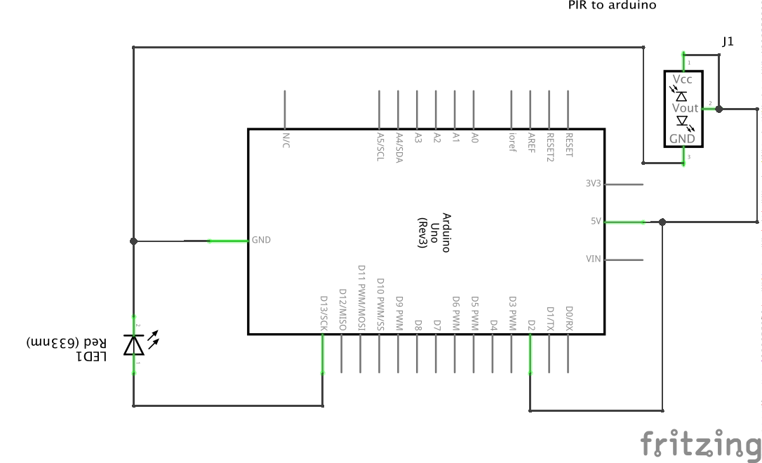
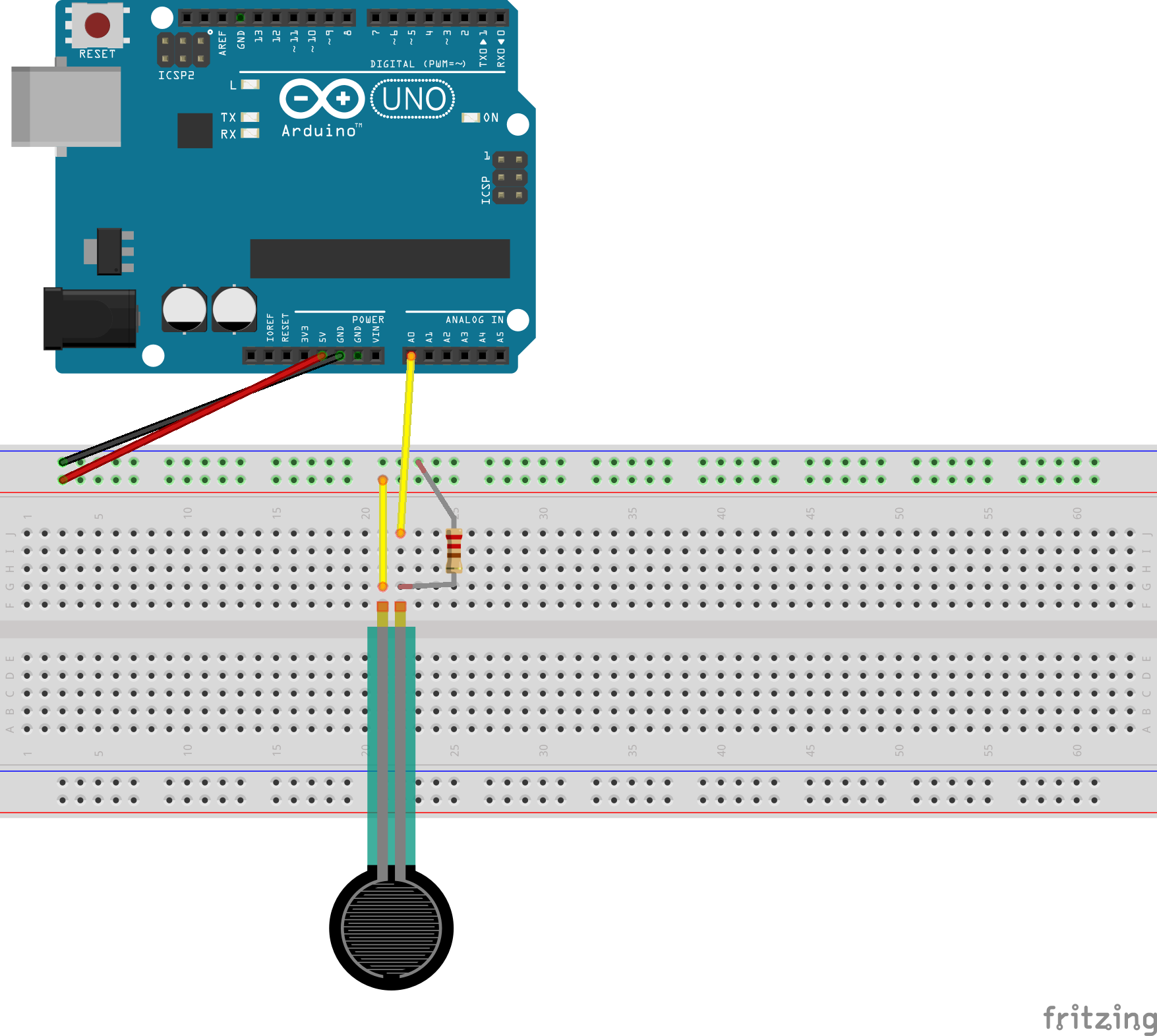
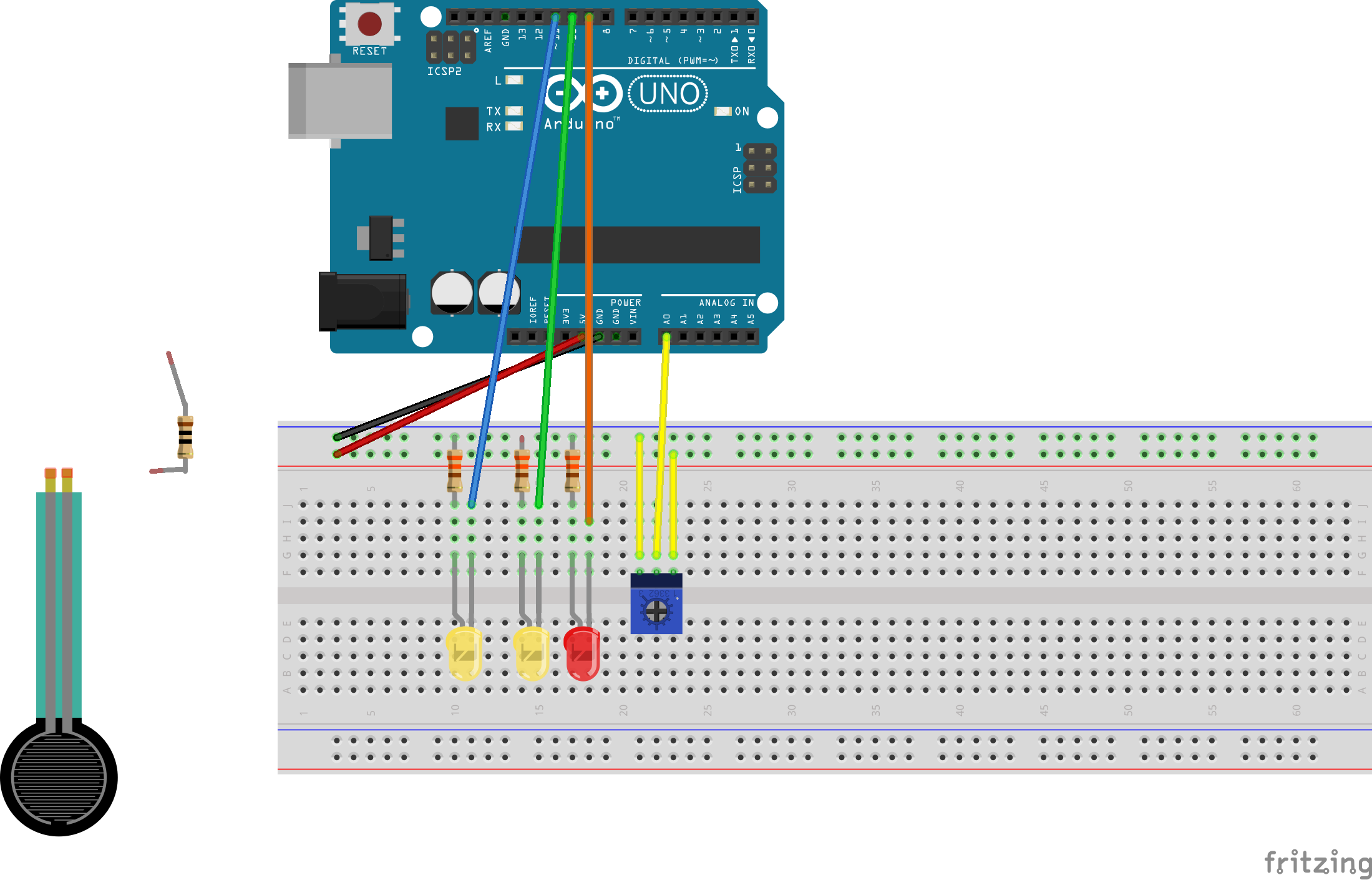
First and foremost, the Servo needs to be connected to a proper source of power for it to work. Make sure to plug in a red wire from the 5V pin to the positive end of the breadboard and to ground it by plugging a black wire from the GND pin to the negative end of the breadboard.
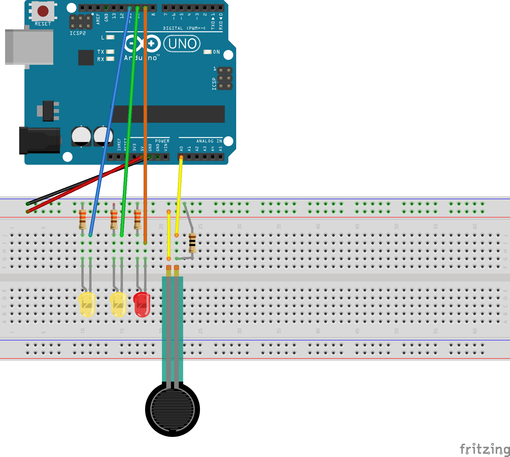
Then, connect your Servo to your breadboard with 3 jumper wires: orange wire (signal) to F8 (breadboard), red wire (+5V) to positive end of breadboard, and brown wire (ground) to negative end of breadboard.
On the same row as the Servo’s orange wire, connect a yellow wire from J8 (breadboard) to pin 9 (Arduino board).
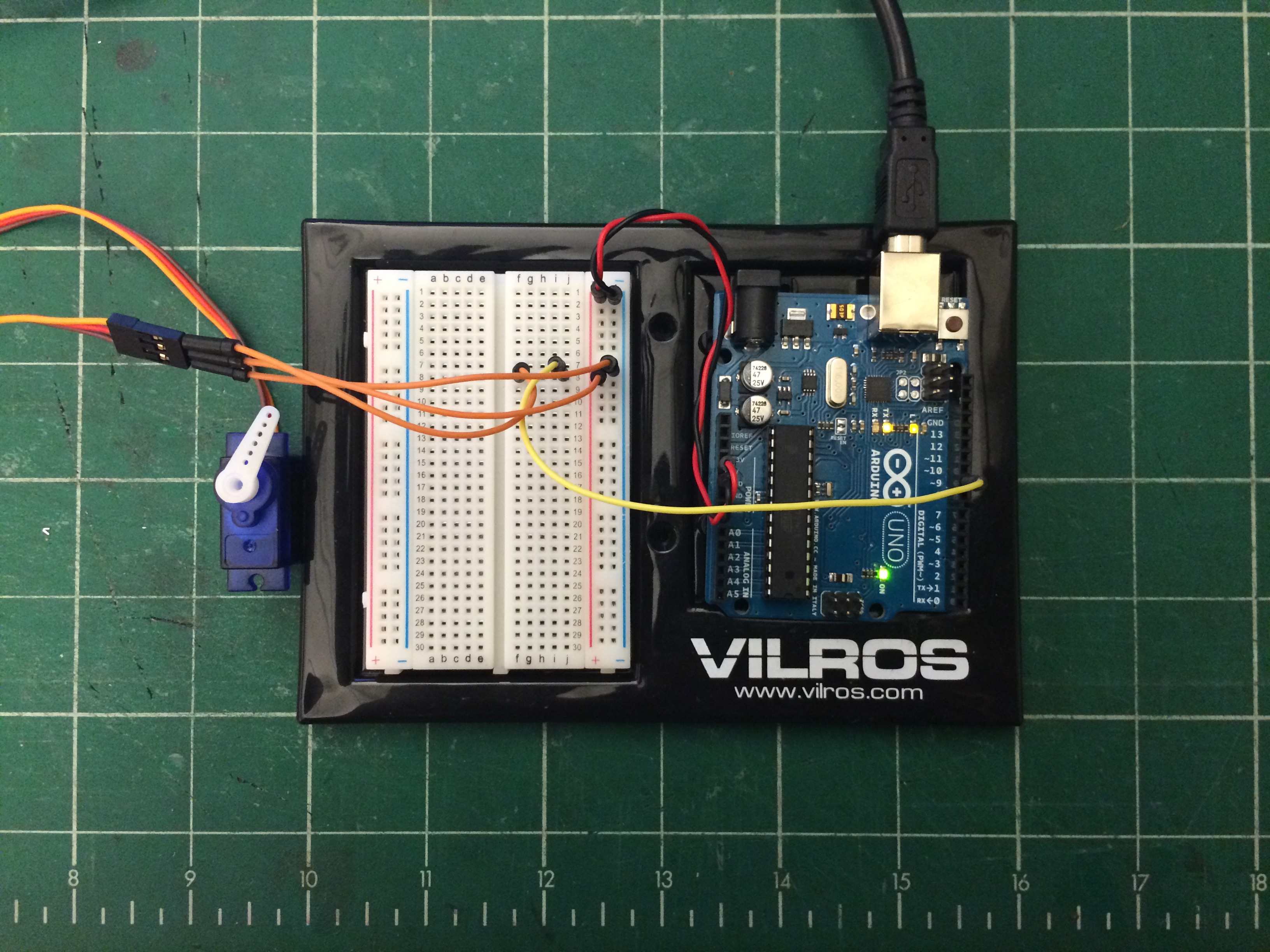
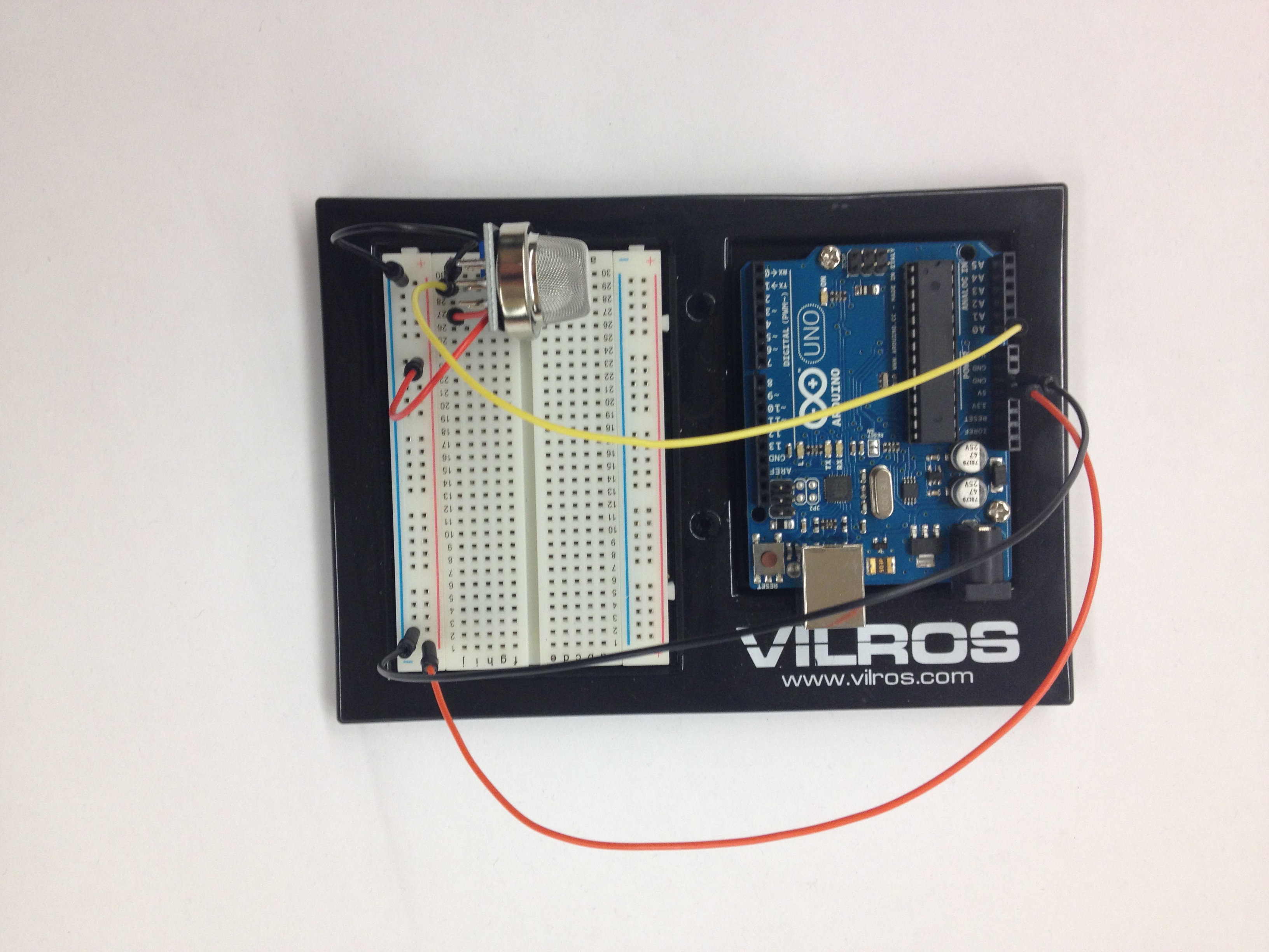
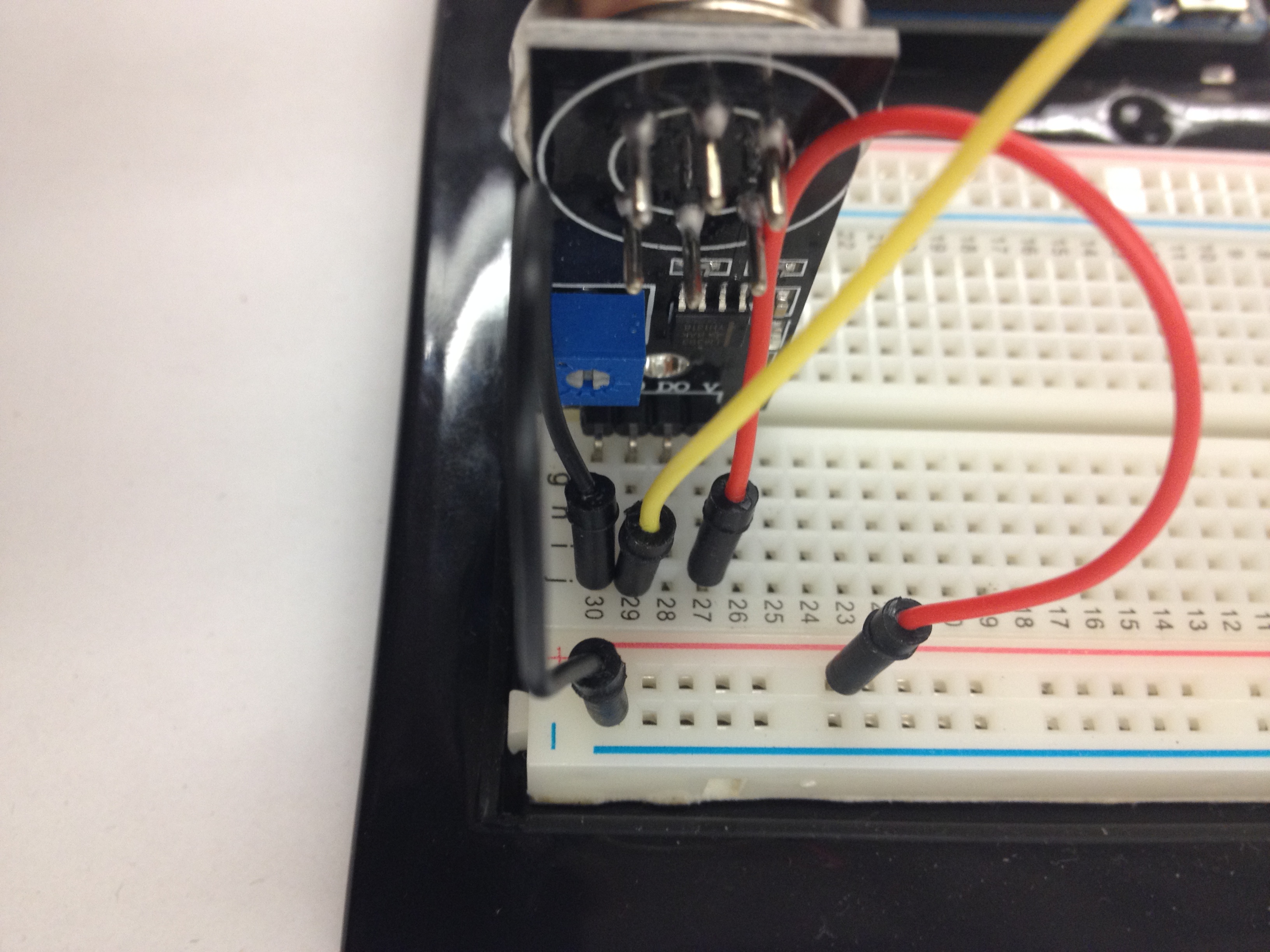
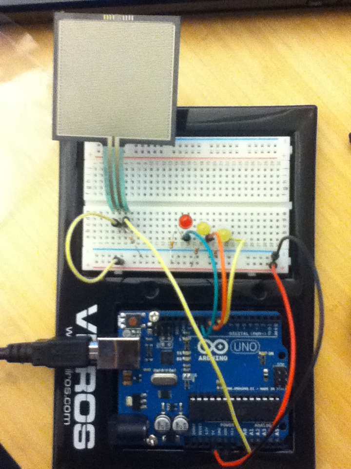
In the end, it should look like this:
Now, let’s make that Servo rotate!
Arduino Code
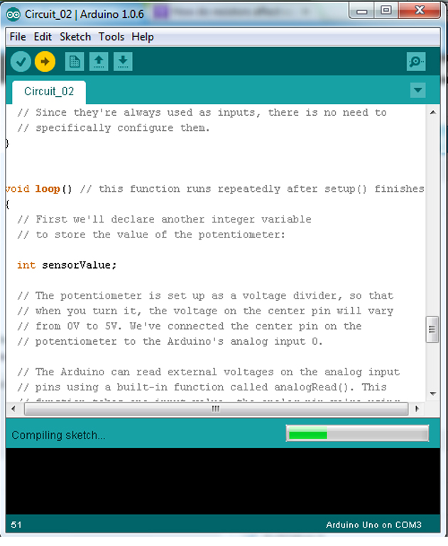
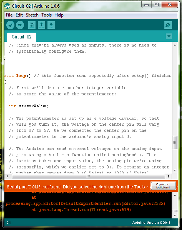
You will need to open up the Arduino interface before we can start writing some code. Remember, your Arduino board is not connected to the computer, so uploading anything is completely impossible. For your Arduino board’s safety, let’s keep it unplugged for now.
Firstly, you must include two different sets of libraries: (1) Servo.h and (2) math.h. These two libraries provide you with the ability to use your Servo and to use the inverse tangent function. Unfortunately, “pi” is not defined in either libraries, including “math.h”, so you must define it yourself.
|
1 2 3 4 5 6 7 8 9 10 11 12 13 14 15 16 17 18 19 20 21 22 23 24 25 26 27 28 29 30 |
// Insert two libraries: Servo.h (for your Servo to work) and math.h (for inverse tangent function). #include #include // Name your servo. I called mine: servo. Servo servo; // Since "pi" has not been defined in any of the available libraries, you must define it yourself. const float pi = 3.14159265359; // Set up some floats: (1) PersonX and PersonY (position of person in relation to a coordinate system), // (2) MotorX and MotorY (position of motor in relation to such coordinate system), // (3) deltaX and deltaY (difference between the position of person in relationship to the position of the motor, // and (4) angleRad and angleDeg (angle of motor to person in both radians and degrees). float PersonX, PersonY; float MotorX, MotorY; float deltaX, deltaY; float angleRad, angleDeg; // In void setup(), make sure to set up a baudrate for your serial monitor // and to mention what pin your Servo is attached to. void setup() { Serial.begin(9600); servo.attach(9); } |
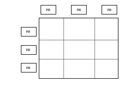
We will now to declare a function that’s argument relies on the use of coordinates rather than separate x and y variables (see Diagram 1).
|
1 2 3 4 5 6 7 8 9 10 11 12 13 14 15 16 17 18 19 20 21 22 23 24 25 26 27 28 29 30 31 32 33 |
// Let's declare a function, and let us call that function motorTurn. void motorTurn(int PersonX,int PersonY) { // PersonX is a person's location on the x-axis, while PersonY is a person's location on the y-axis. // As mentioned before, deltaX and deltaY is the difference between the position of a person in relation to the position of the motor. deltaX = PersonX - MotorX; deltaY = PersonY - MotorY; if (deltaX > 0 ) { angleRad = atan(deltaY/deltaX); } else { angleRad = pi + atan(deltaY/deltaX); } angleDeg = angleRad * (180/pi); // Let us convert the angle from radians (angleRad) to degrees (angleDeg). if (angleDeg>180) { angleDeg = -(360-angleDeg); // Now, let us keep the angles between -180 to 180 degrees, for the sake of clarity. } Serial.print("Coordinate: "); Serial.print(PersonX); Serial.print(","); Serial.println(PersonY); Serial.print("Angle: "); Serial.println(angleDeg); Serial.println(" degrees"); servo.write(angleDeg); // This should make the Servo rotate. delay(1000); } |
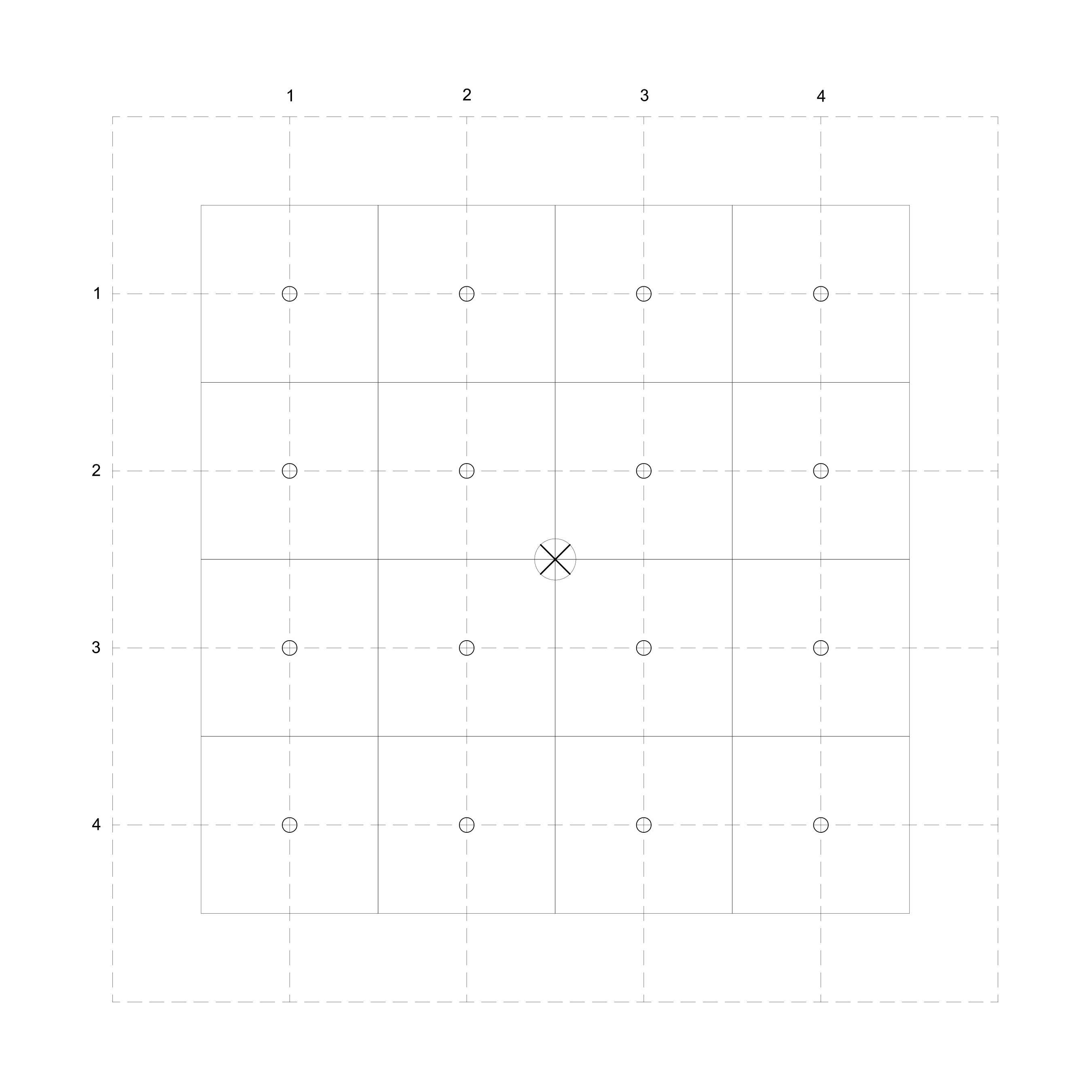
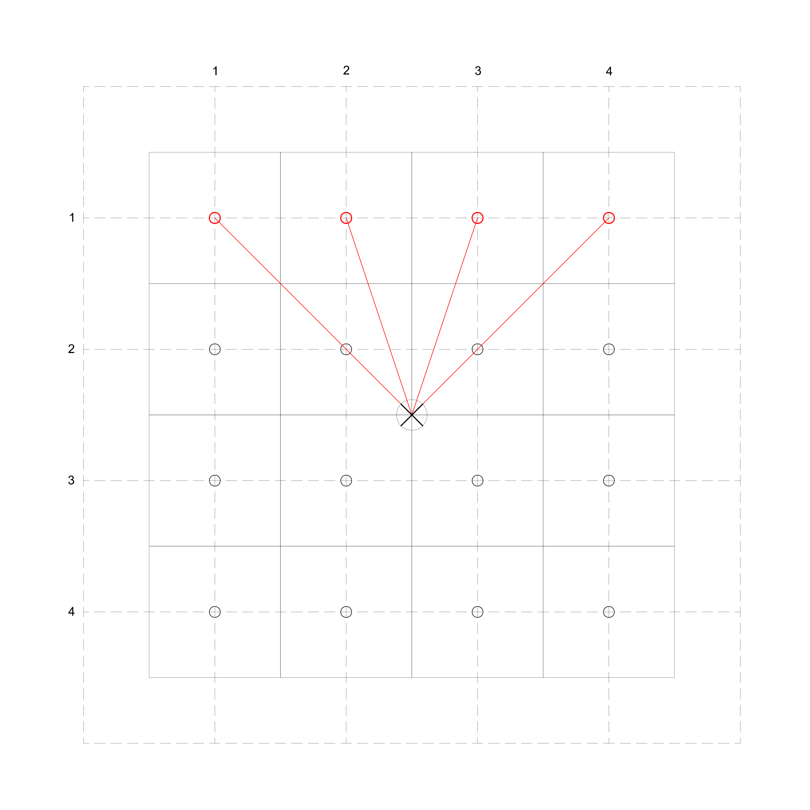
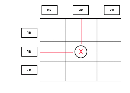
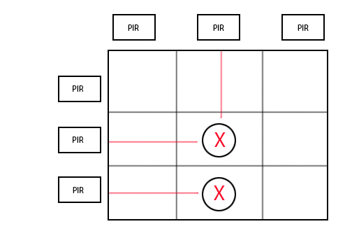
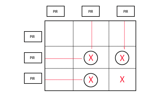
Within the loop function, we will state the position of the motor in relation to the grid (see Diagram 1). Now, we want the motor to angle towards the points located around it (which are diagrammed as circles). In the code below, we will focus on 4 points (see Diagram 2).
|
1 2 3 4 5 6 7 8 9 10 11 12 13 14 15 16 17 18 19 |
void loop() { // Give the motor a position: MotorX = 2.5; MotorY = 2.5; // Now give the person a series of positions: motorTurn(1,1); delay(1000); motorTurn(2,1); delay(1000); motorTurn(3,1); delay(1000); motorTurn(4,1); delay(1000); motorTurn(5,1); delay(1000); } // The motor should now rotate towards the position of the person and eventually follow the person through each position within the series provided. |
Now plug in your Arduino, upload the code and watch your Servo’s arm rotate! You can also check out the angle of the arm in relation to the coordinate in your serial monitor!
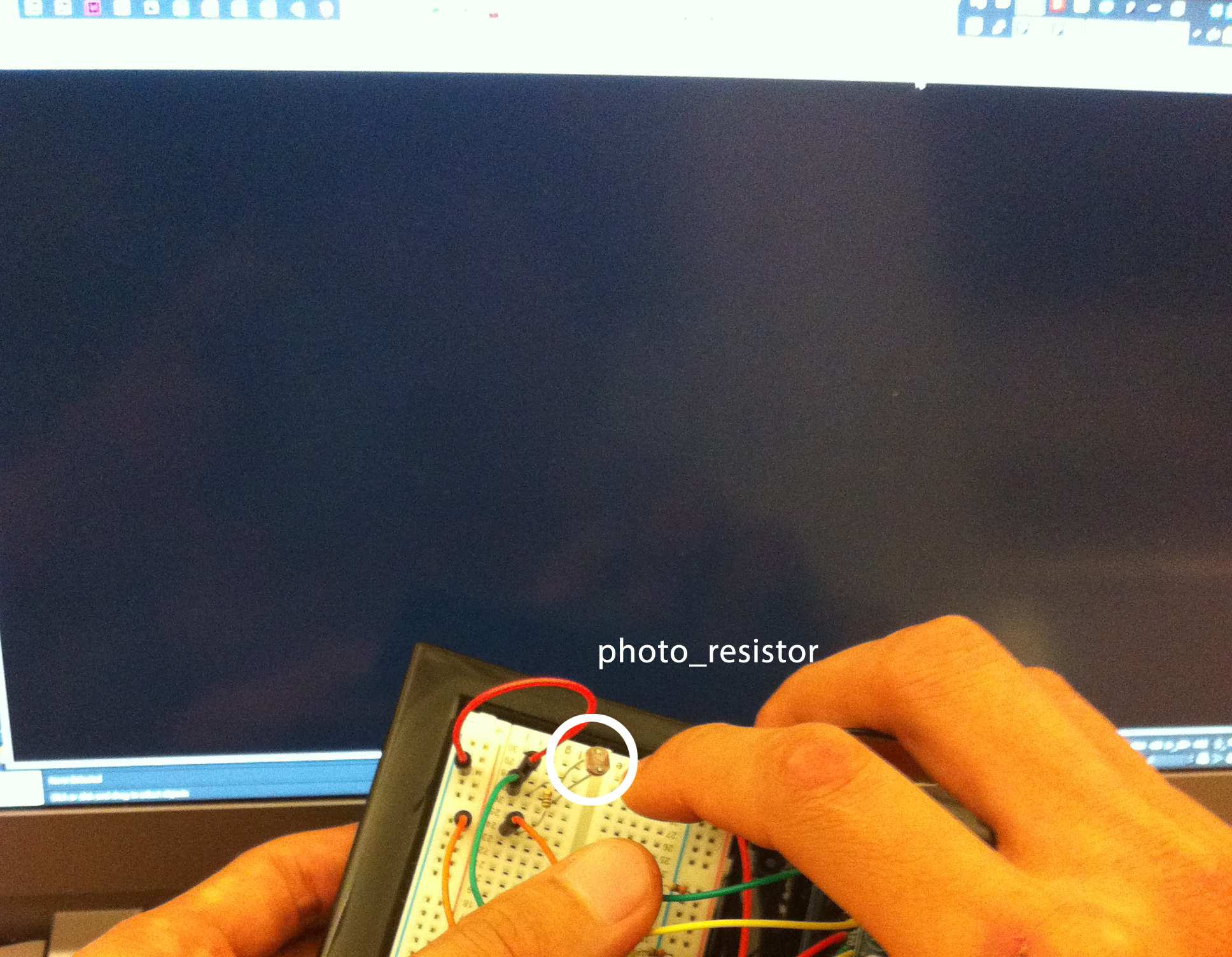
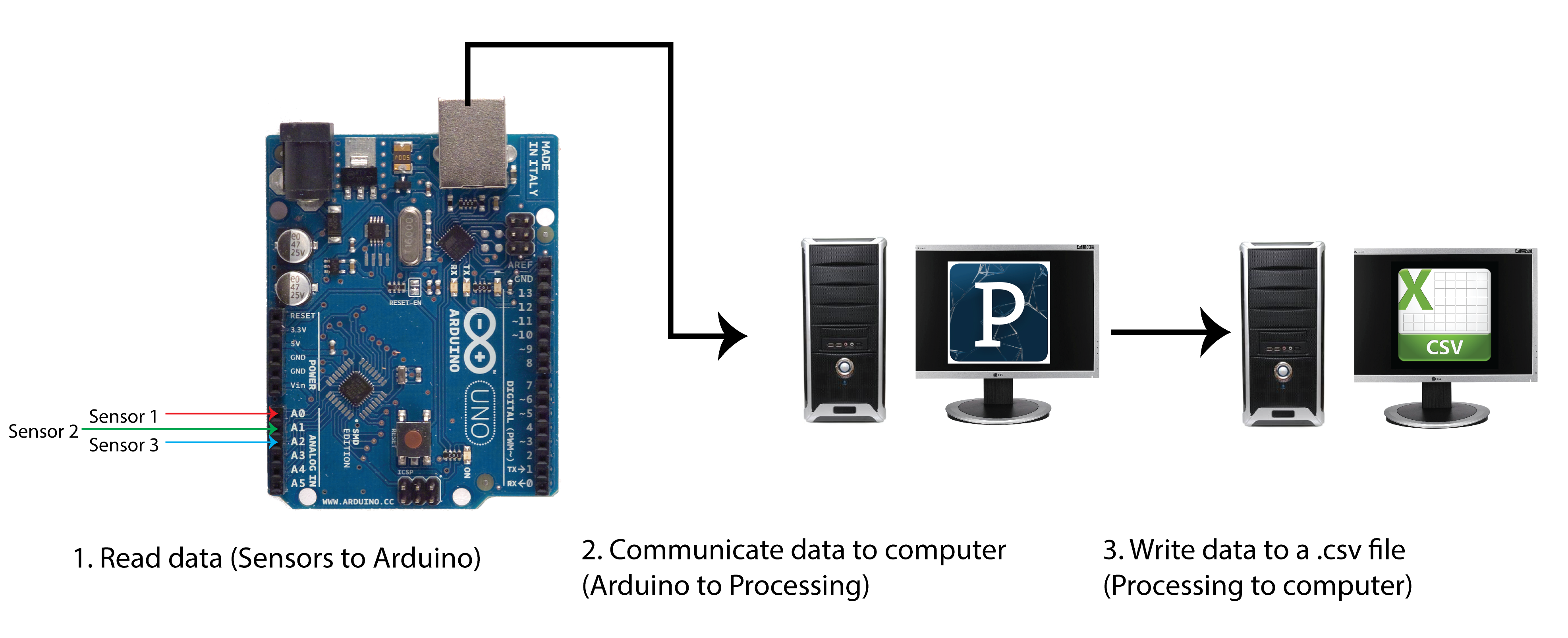
If you like, you can expand on this tutorial by including sensors into the equation! Instead of manually giving a set of coordinates, you can collect coordinates through a series of sensors within a built grid. The motor’s arm will rotate to the individual’s position within that grid, thanks to the sensor!


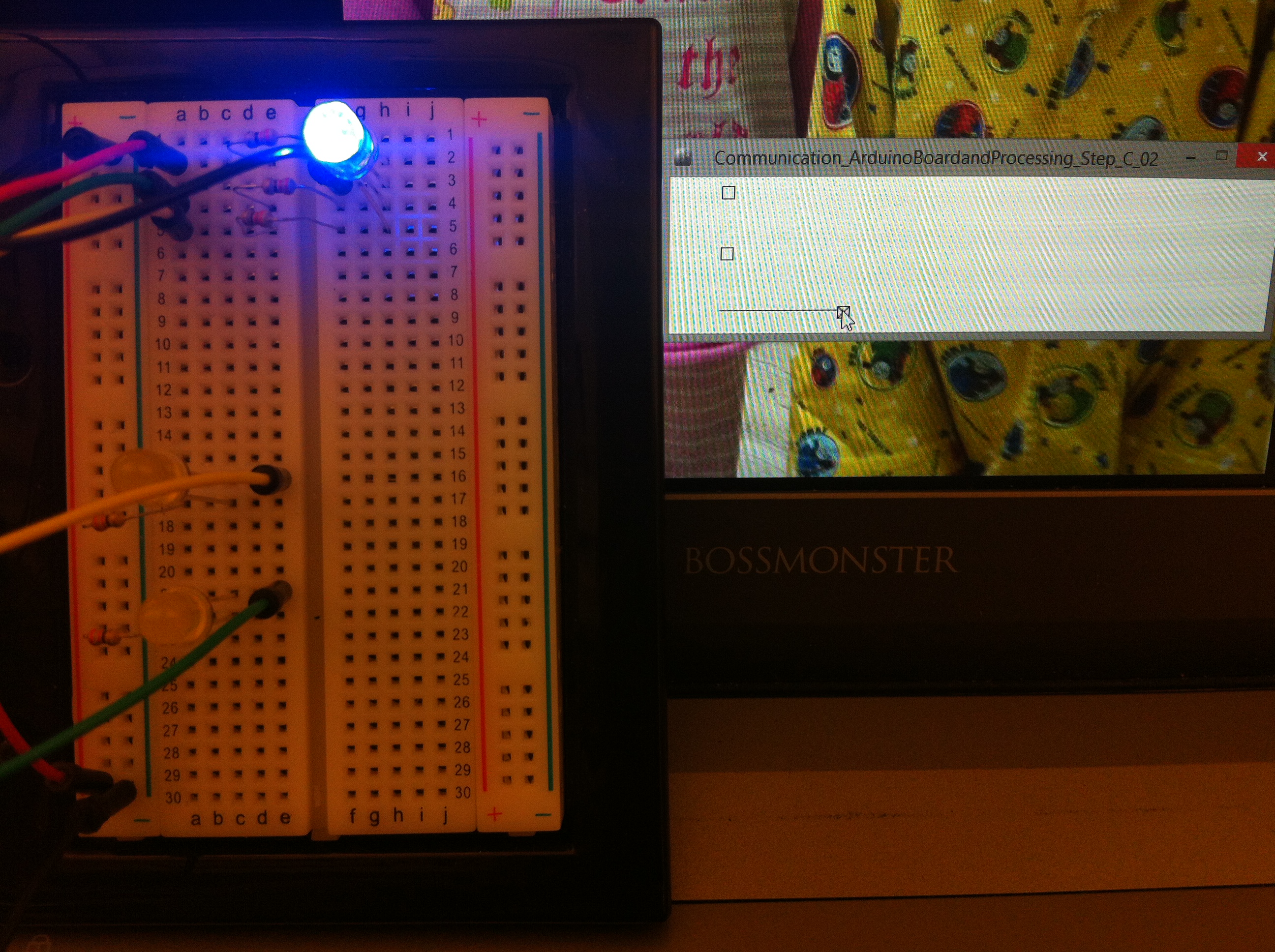
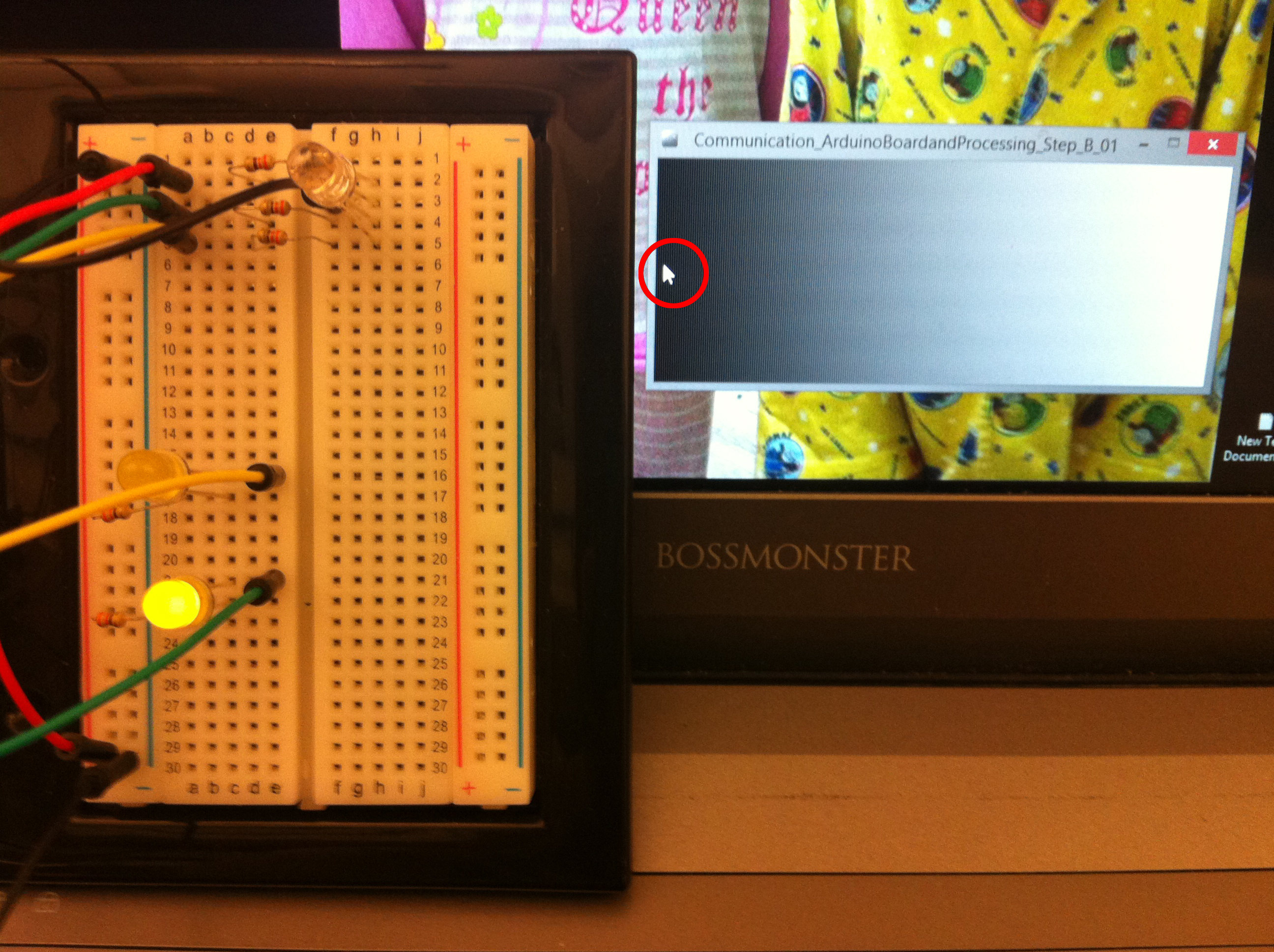
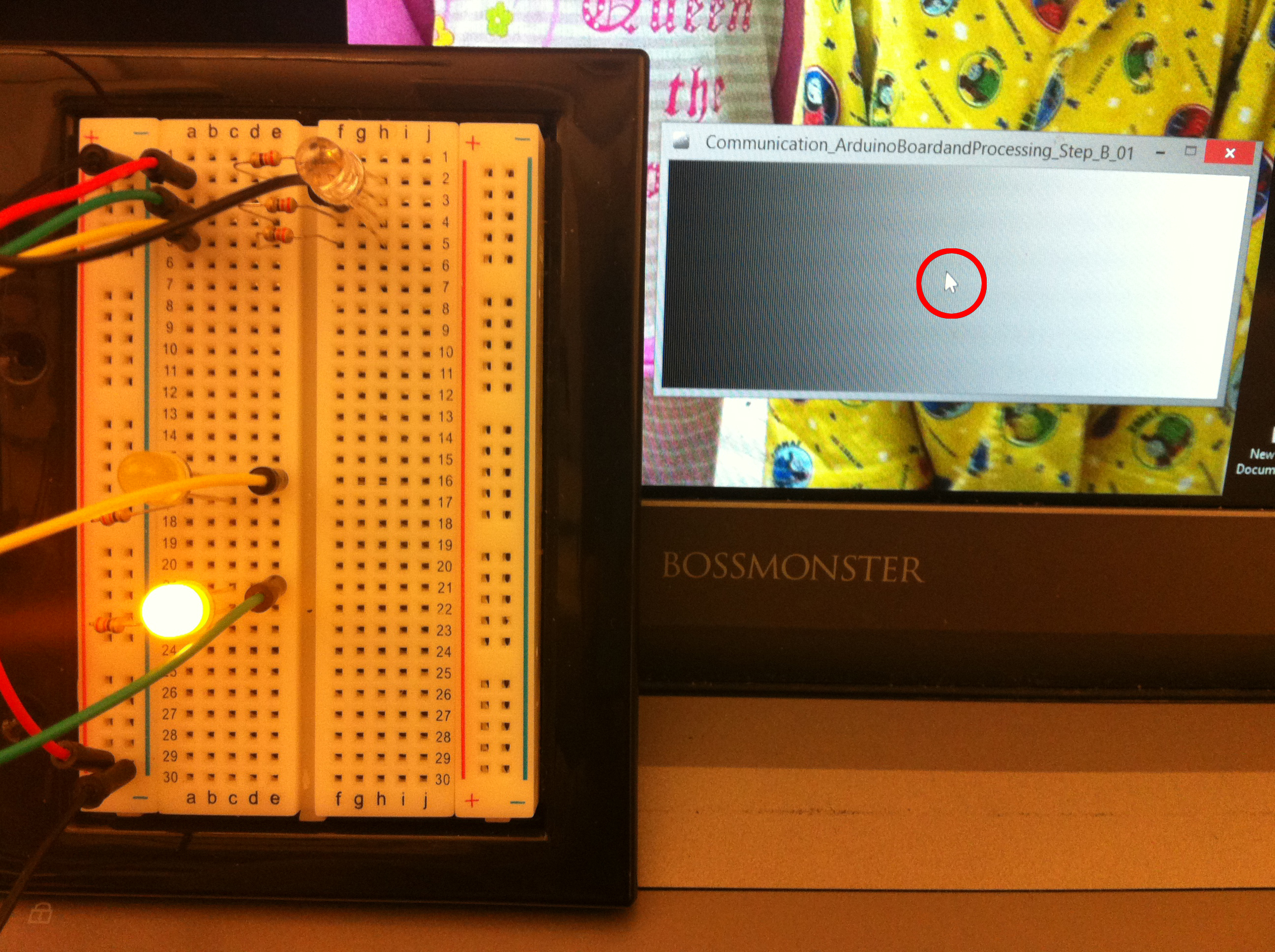
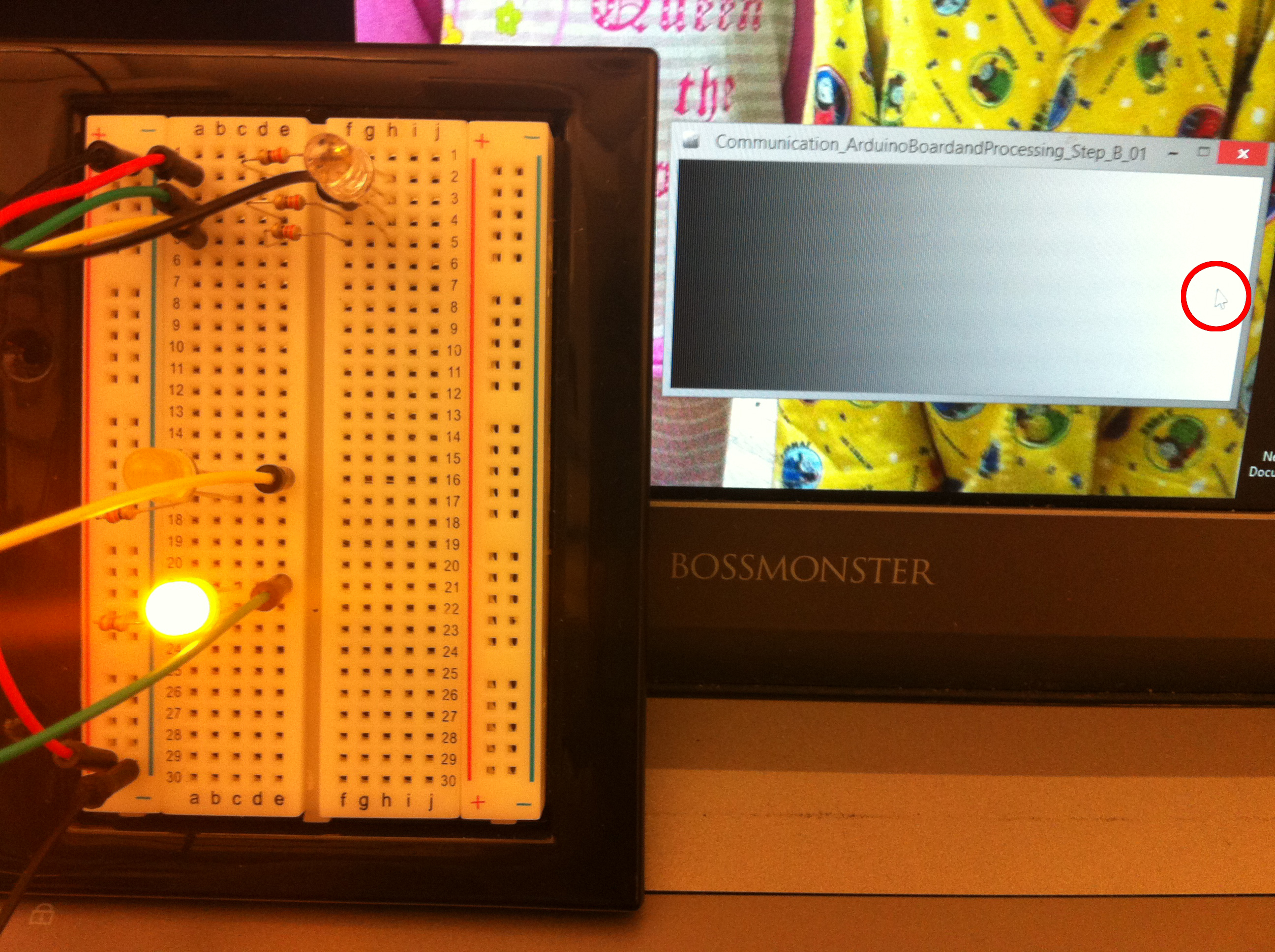
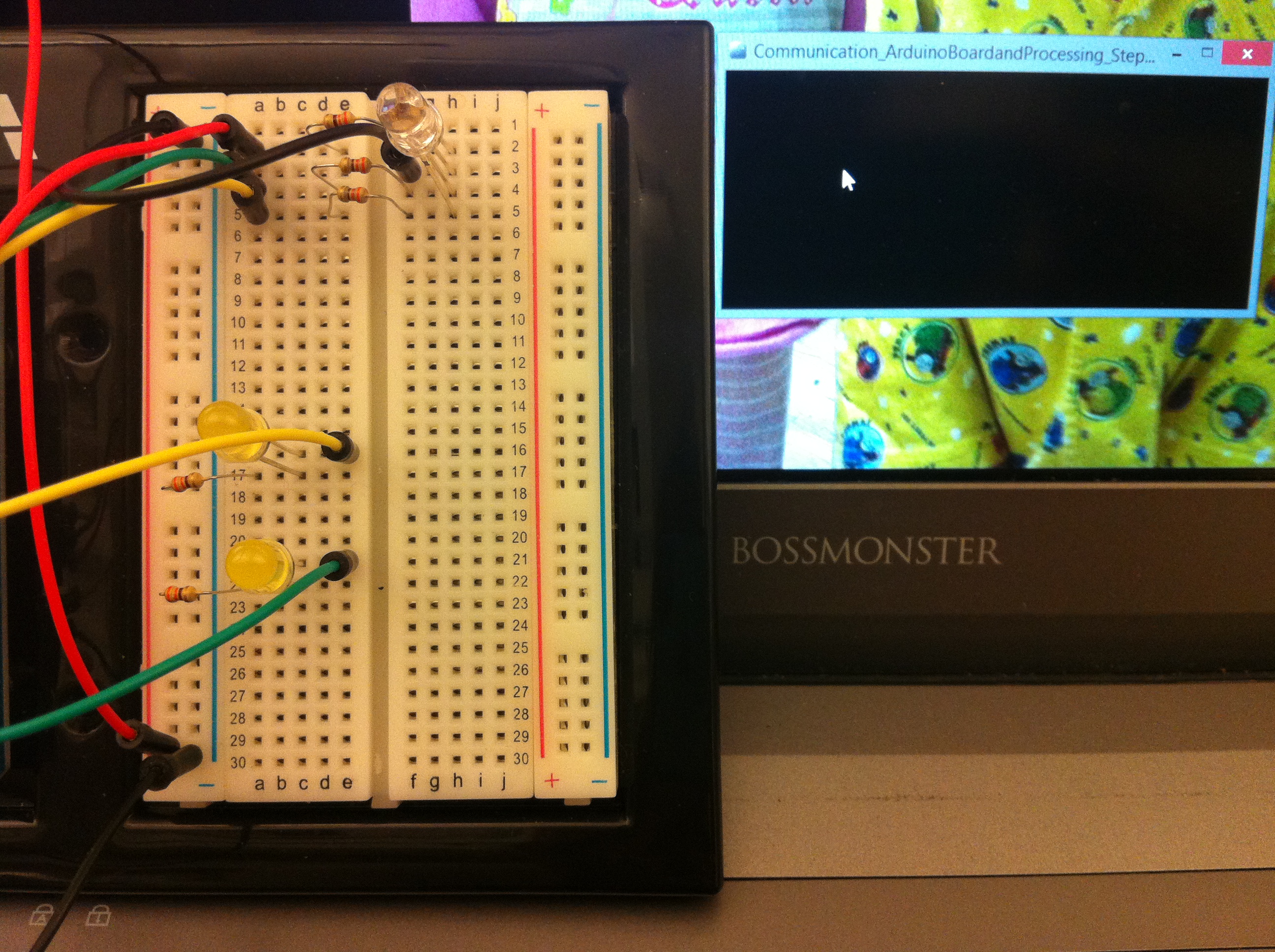 Click on the Processing sketch to blink an LED


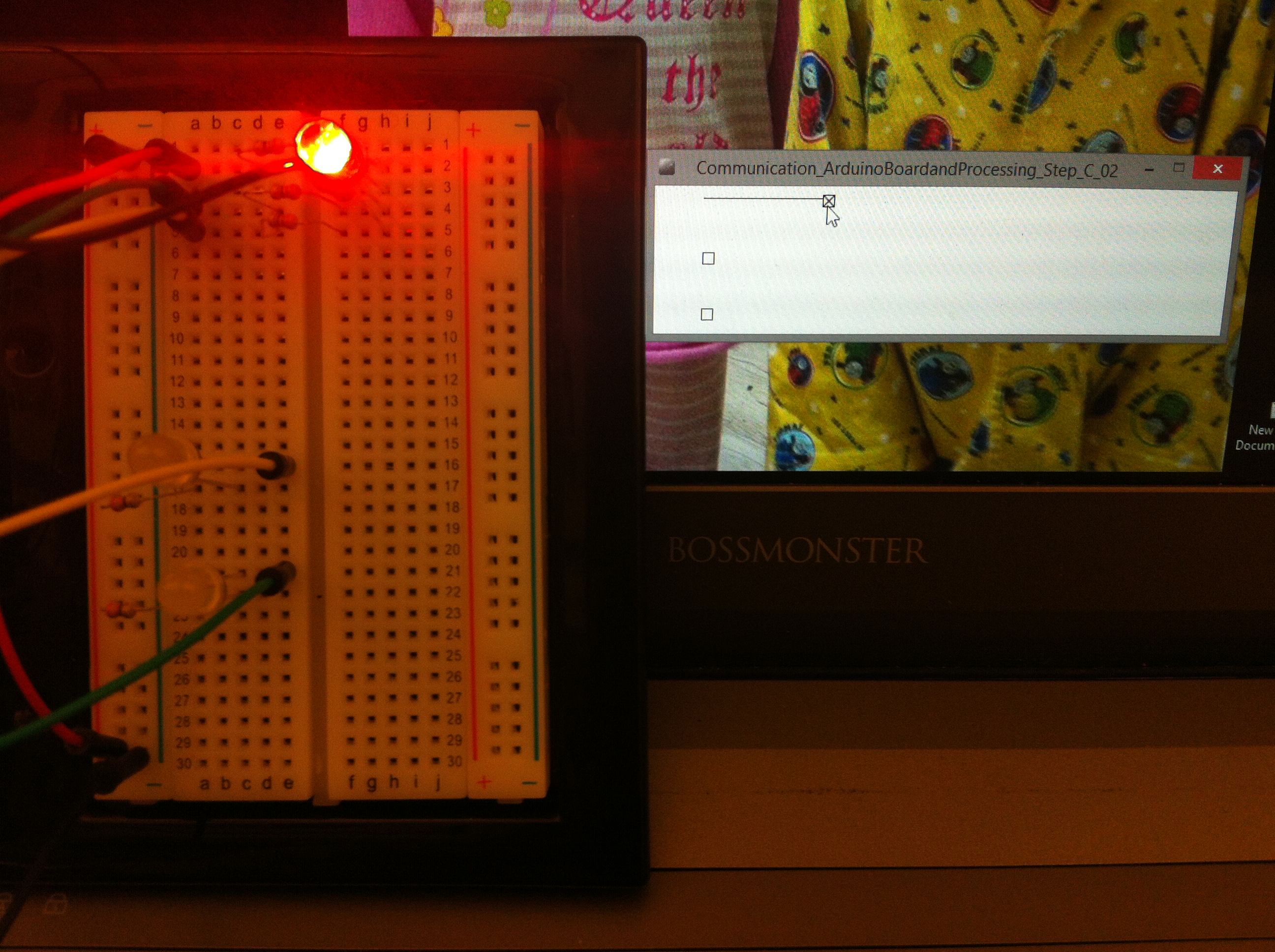
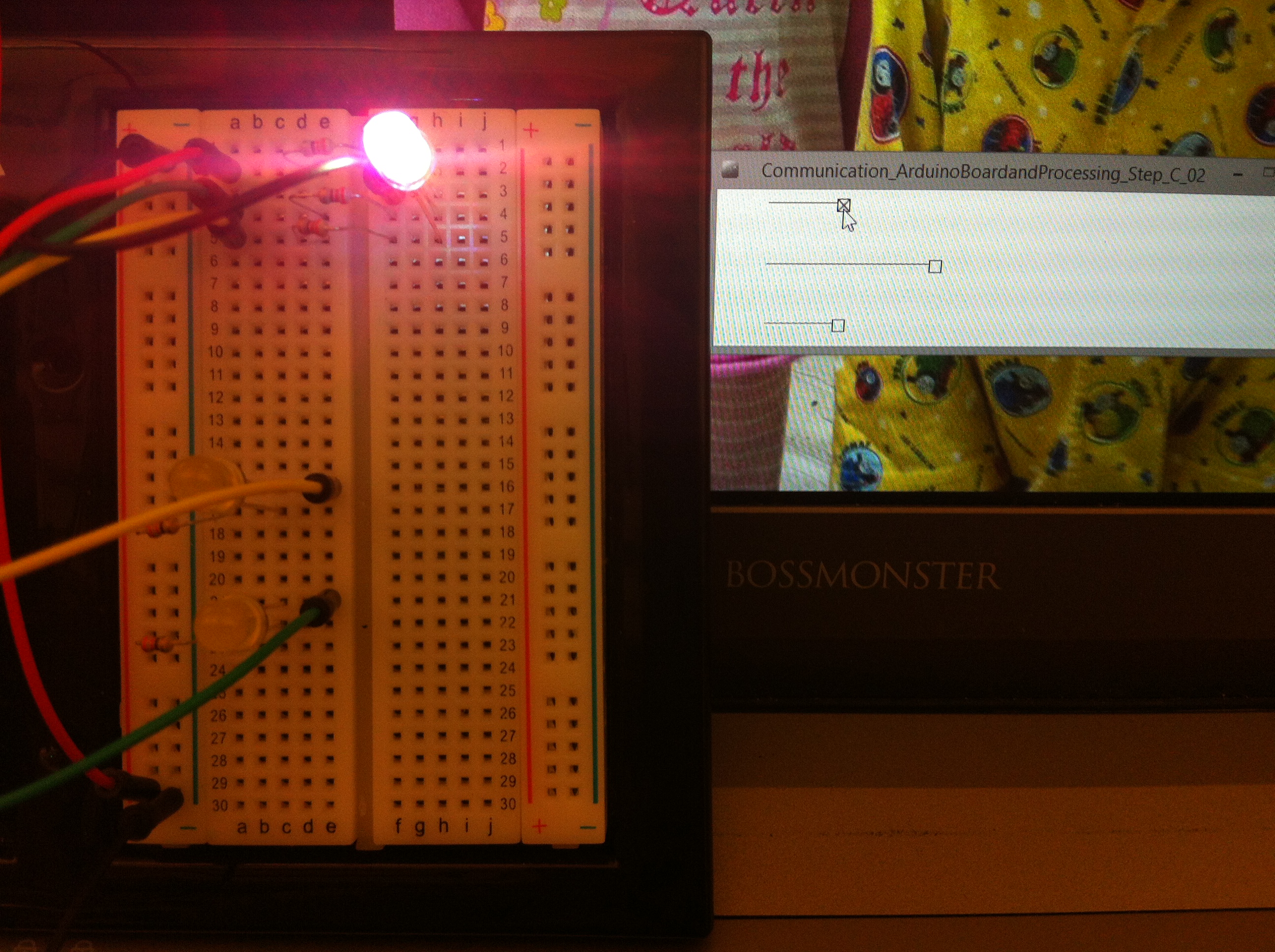
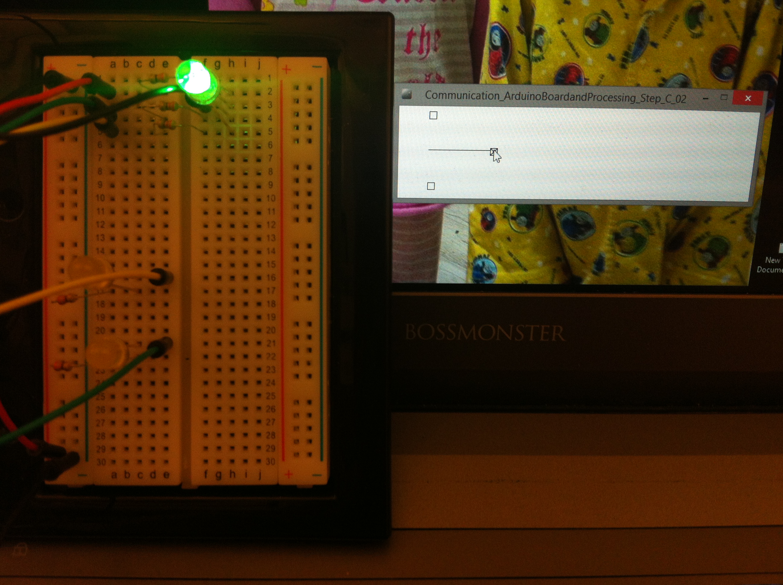 Changing RGB LED brightness with analogWrite function based on handle, value = green